System Address Mapping
Élan™SC520 Microcontroller User’s Manual 4-3
4.3 OPERATION
There are three types of system bus masters supported on the ÉlanSC520 microcontroller:
the Am5
x
86 CPU, the PCI bus, and the GP bus DMA controller.
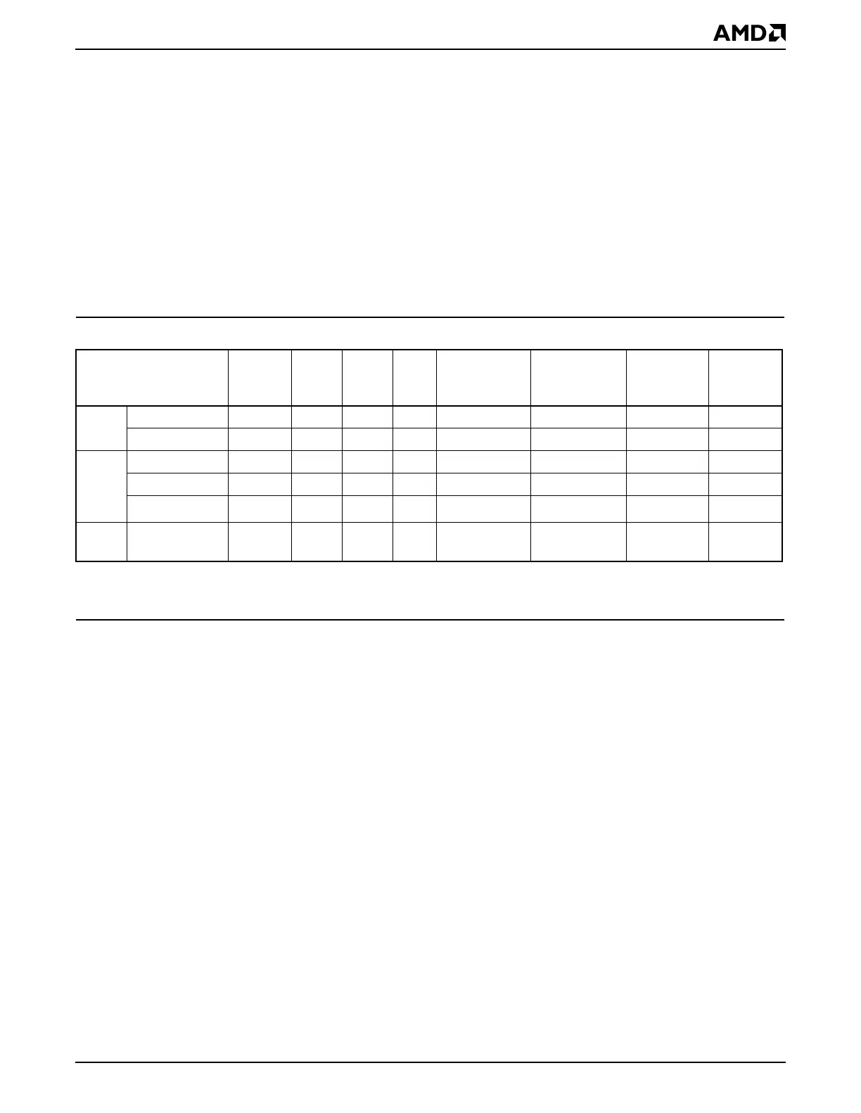
As shown in Table 4-3, each of the three bus masters can access specific types of address
space.
■ The Am5
x
86 CPU and the PCI bus each implement separate memory and I/O address
space.
■ The PCI bus further specifies a separate space for device configuration registers.
■ The GP bus DMA controller supports fly-by transfers between GP bus devices and
SDRAM; therefore, as a bus master, it supports memory space only.
The Am5
x
86 CPU and PCI bus definition support separate memory and I/O address spaces
(I/O space is limited to 64 Kbytes on the CPU). The
PCI Local Bus Specification,
Revision
2.2
, further defines a separate space for configuration registers.
The ÉlanSC520 microcontroller divides these address spaces as follows:
■ Memory space
– ROM/Flash space for data and code storage using up to three chip selects (accessible
only by the CPU)
– SDRAM space for data and code storage
– GP bus memory space (accessible only by the CPU)
– PCI bus memory space (accessible only by the CPU and PCI bus masters)
– Internal memory-mapped configuration region (MMCR) registers (accessible only by
the CPU)
■ I/O space
– Integrated PC/AT-compatible peripherals (accessible only by the CPU)
– Configuration Base Address (CBAR) register (Port FFFCh) to set the MMCR’s base
address (accessible only by the CPU)
Table 4-3 Bus Master Address Spaces
Bus Master and
Address Space SDRAM ROM
GP
Bus
PCI
Bus
Integrated
PC/AT
Peripherals
Integrated
Non-PC/AT
Peripherals
Memory-
Mapped
Registers
CBAR
Register
CPU Memory ✔✔✔✔ ✔ ✔
I/O ✔✔ ✔ ✔
PCI
Bus
Memory ✔✔
I/O ✔
Configuration
1
Notes:
1. Accessed indirectly by the CPU via the PCI configuration registers in I/O space.
GP-
DMA
Memory ✔