ROM/Flash Controller
12-6 Élan™SC520 Microcontroller User’s Manual
ROM devices are accessible by the Am5
x
86 CPU only. Normal operation of the ÉlanSC520
microcontroller is not guaranteed if an external PCI master or GP-DMA cycle results in a
ROM access.
The addresses for ROM devices are always provided via the GP bus, independently of
whether the data pins of the ROM are connected to the GP bus or SDRAM bus.
The ROM controller never bus-sizes read accesses to the Am5
x
86 CPU. In other words,
bs16
and bs8 are never asserted for a ROM read access. Rather, the ROM controller
gathers as much data as the Am5
x
86 CPU is requesting for read accesses. To accomplish
this, the ROM controller monitors the internal byte enable signals, be3
–be0, and the
cacheability status of the access. Based on the byte enables, the ROM controller returns
one to four bytes for non-burst Am5
x
86 CPU cycles and up to an entire cache line, 16 bytes,
for burst accesses.
The ROM controller does not support burst-write or multiple data operations during write
cycles. Writes to ROM devices typically have no performance issues. The ROM controller
returns rdy
, rather than brdy, to the Am5
x
86 CPU during write operations. In addition, the
Am5
x
86 CPU signals bs8 and bs16 are asserted based on data size of the selected ROM
device.
12.5.1.1 Supported Device Types
The ROM controller supports two ROM device types:
■ Non-page-mode ROM—A ROM device that always has the same access delay,
regardless of how much data is requested from the ROM.
■ Advanced page-mode ROM—These devices improve performance by allowing fast
multiple access of data within the same memory page. The ROM controller has no upper
limit on the page size of the ROM device and works with any device that supports a
page size of four. However, after the fourth entry in the page, the ROM controller issues
a new initial access.The page is opened during the initial access, allowing faster data
reads from subsequent locations within the page simply by strobing the lower address
bits.
Non-page-mode and advanced page-mode ROMs do not require a clock signal.
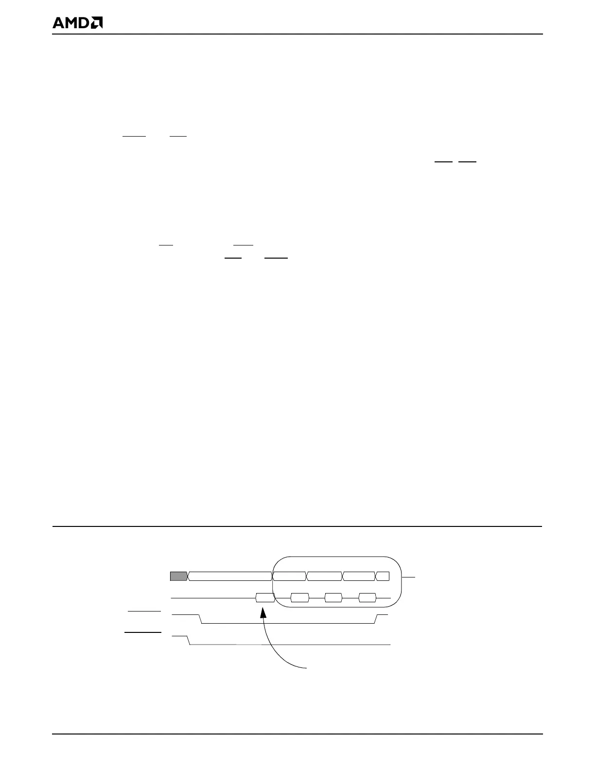
Figure 12-3 illustrates a read of four words from a 16-bit advanced page-mode ROM. Note
that the write buffer associated with the SDRAM controller has no relevance for the ROM
controller, because it applies only to SDRAM accesses.
Figure 12-3 Page-Mode ROM: Fetching Four Words from a 16-Bit ROM
- - - 0h - - - 2h - - - 4h - - - 6h
GPA25–GPA0
MD31–MD0
ROMRD
BOOTCS
Initial memory page opened here
Notes:
Subsequent reads occur
within the same memory
page, by changing the lower
address bits only, resulting in
a fast access of eight bytes.
Bytes 0-1 Bytes 2-3 Bytes 4-5 Bytes 6-7