General-Purpose Bus Controller
13-16 Élan™SC520 Microcontroller User’s Manual
Figure 13-8 Timing Diagram of an Am85C30 Interface
13.5.9 Bus Cycles
13.5.9.1 8-Bit Data Access of an 8-Bit I/O Device
During an 8-bit access to 8-bit I/O devices, GPD7–GPD0 is used to transfer data between
the CPU and external devices. For an 8-bit memory-mapped I/O device, GPMEMWR
and
GPMEMRD
are used instead of GPIOWR and GPIORD.
Figure 13-9 shows the timing diagram of an 8-bit device access of an 8-bit I/O device.
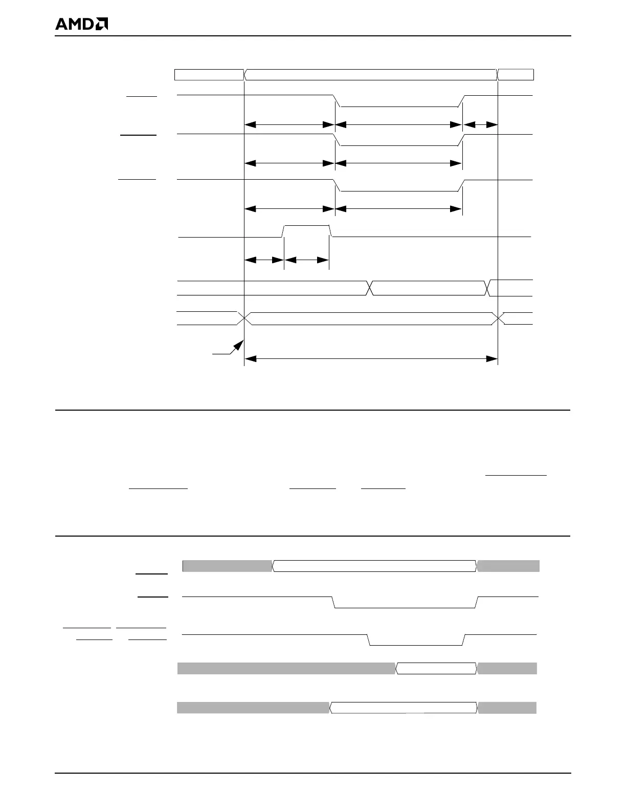
Figure 13-9 8-Bit Data Access of an 8-Bit I/O Device
Address Valid
GPA1
–GPA0
GPCSx
GPIORD
GPALE
90 ns
30 ns
150 ns
270 ns
Beginning of a bus cycle
(Not needed)
30 ns
30 ns
GPIOWR
90 ns
150 ns
90 ns
Read Data
Write Data
GPD7
–
GPD0
GPD7
–
GPD0
Notes:
1. This example assumes that a 33.333-MHz crystal is being used in the system.
Read Data
GPA25
–
GPA0,
GPCSx
GPMEMRD, GPMEMWR,
GPD7–GPD0
Write Data
GPBHE
GPD7–GPD0
GPIORD, or GPIOWR