Programmable Interrupt Controller
Élan™SC520 Microcontroller User’s Manual 15-11
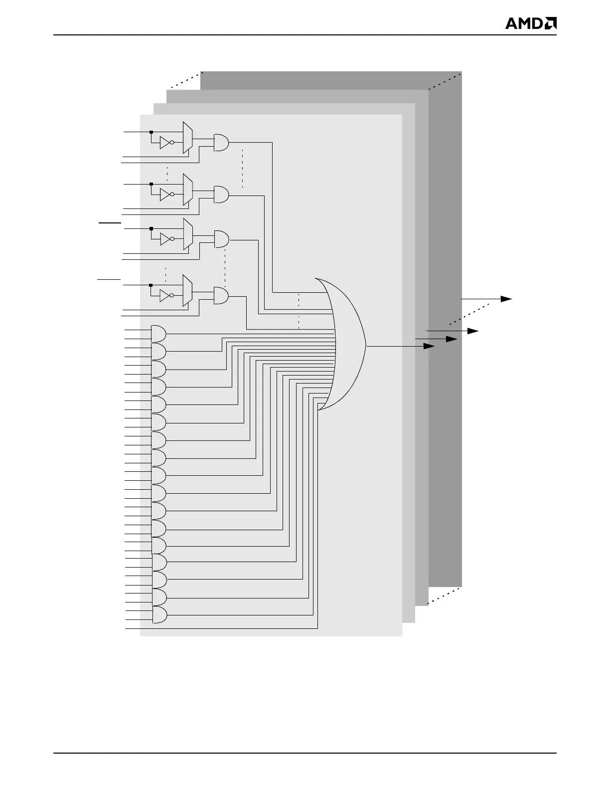
Figure 15-3 Interrupt Source Routing
irq_p1
pit_tmr0_irq
pit_timr1_irq
pit_tmr2_irq
gp_tmr0_irq
gp_tmr1_irq
gp_tmr2_irq
uart1_irq
uart2_irq
ecc_irq
wdt_irq
rtc_irq
0
1
GPIRQ0
polarity0
irq_p2
irq_p3
irq_p22
Channel 1 Router
Channel 2 Router
Channel 3 Router
Channel 22 Router
src_enb0
src_enb15
src_enb16
src_enb17
src_enb18
src_enb19
src_enb20
src_enb21
src_enb22
src_enb23
src_enb24
src_enb25
src_enb26
irq[1]_trig
pci_irq
src_enb27
0
1
GPIRQ10
polarity10
src_enb10
1
0
INTA
polarity11
src_enb11
1
0
INTD
polarity14
src_enb14
ssi_irq
wpv_irq
src_enb28
src_enb29
gpdma_bc_irq
ice_irq
src_enb30
src_enb31
ferr_irq
Notes:
All the 32 hardware interrupt sources are common to all the 22 channel routers. The polarity control signal per
external interrupt source is also common to all the 22 channel routers. The decoder for the enable signals is not
shown; only the decoded representation of the signals is shown. Each channel router has its unique internally-
generated hardware interrupt trigger, and only irq[1]_trig is shown for channel router 1.