System Arbitration
8-14 Élan™SC520 Microcontroller User’s Manual
■ Clock #11: The Am5
x
86 CPU samples cpu_rdy, which ends the write-back cycle. The
Am5
x
86 CPU has also sampled cpu_hold asserted and surrenders the bus by asserting
cpu_hlda.
Note: This write-back cycle is for illustration purposes only; the actual write-back cycle
would consist of multiple data phases.
■ Clock #12: The Am5
x
86 CPU deasserts hitm one clock after cpu_rdy ends the write-
back cycle.
■ Clock #13: The CPU bus master samples hitm deasserted and starts the bus cycle.
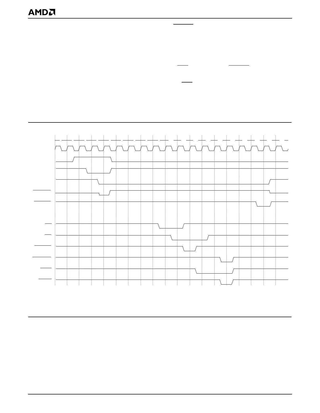
8.4.4.3 CPU-to-PCI Cycle
Figure 8-8 shows an Am5
x
86 CPU-to-PCI bus cycle. The Am5
x
86 CPU cycle is either a
read cycle or a write cycle with write posting disabled.
Figure 8-8 CPU-to-PCI Cycle
Notes:
The clk signal denotes the 33-MHz clock source and represents both the CPU clock and the PCI clock. This diagram
does not represent the full synchronization of signals between these clock domains.
The following sequence annotates the Am5
x
86 CPU-to-PCI cycle shown in Figure 8-8.
■ Clock #2: The Am5
x
86 CPU asserts breq to request the CPU bus. The CPU bus arbiter
will grant the bus to the CPU when the current bus owner’s cycle is completed. The
pending Am5
x
86 CPU cycle is to PCI.
■ Clock #3: The CPU bus arbiter deasserts cpu_hold to the Am5
x
86 CPU to grant the
bus to the Am5
x
86 CPU. The deassertion of cpu_hold would be delayed if the CPU bus
was not idle or if another higher priority master was requesting the CPU bus.
1 2 3 4 5 6 7 8 9 10 11 12 13 14 15 16 17 18 19
clk
breq
cpu_hold
cpu_hlda
cpu_ads
cpu_rdy
req
gnt
FRAME
DEVSEL
IRDY
TRDY