UART Serial Ports
21-2 Élan™SC520 Microcontroller User’s Manual
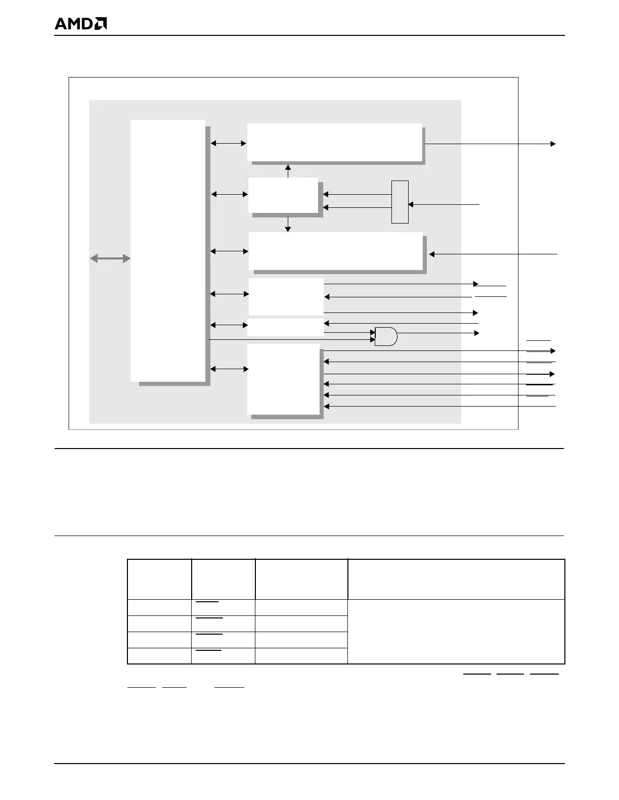
Figure 21-1 UART Block Diagram
21.3 SYSTEM DESIGN
UART 2 shares signals with the PIO31–PIO28 signals, as shown in Table 21-1. When
enabled, the multiplexed signals shown in Table 21-1 either disable or alter any other
function that uses the same pin.
Both UARTs can work with full modem control signals (SOUTx, SINx, CTSx, RTSx, DSRx,
DTRx
, RINx, and DCDx) or with two wires only (SOUTx and SINx). If only two wires are
used, the unused input port pins can be left unconnected. (There are internal pullup resistors
on these signals.)
Table 21-1 UART Signals Shared with Other Interfaces
PIO
(Default)
Function
Interface
Function Control Bit Register
PIO31 RIN2
PIO31_FNC PIO31–PIO16 Pin Function Select
(PIOPFS31_16) register (MMCR offset C22h)
PIO30 DCD2
PIO30_FNC
PIO29 DSR2
PIO29_FNC
PIO28 CTS2
PIO28_FNC
Transmitter
Interrupt
Configuration
rx_dma_req
uart_irq
tx_dma_req
SOUTx
SINx
clk_uart
RTSx
CTSx
DSRx
RINx
DTRx
DCDx
DMA Control
Prescaler
(18.432 MHz)
18.432 MHz
1.8432 MHz
From
clocks
To/from DMA
To PIC
Registers
out2
GP Bus
gptc
tx_dack
Élan™SC520 Microcontroller
Modem
Control
Baud
Generator
TX Hold Register
TX FIFO
TX shift register
Receiver
RX FIFO
RX Buffer Register
RX shift register
UART
rx_dack