System Initialization
Élan™SC520 Microcontroller User’s Manual 3-7
errors will occur when writing data smaller than a 32-bit doubleword. For a more detailed
discussion of ECC, see “Error Correction Code (ECC)” on page 10-16.
3.3 IDENTIFYING THE CPU CORE
Information about the integrated Am5
x
86 CPU core is available by reading the processor
DX register after a system reset and by using the CPUID instruction at any time. The CPUID
instruction is available on later model 32-bit processors from all leading x86 vendors and
allows programs to determine information about the CPU, including the manufacturer,
cache type, and availability of a floating point unit (FPU). By using the CPUID instruction,
software can determine the type of CPU running the system. For example, software could
detect that it is running on an Am5
x
86 CPU and perform the appropriate action.
The ÉlanSC520 Microcontroller Revision ID (REVID) register (MMCR offset 00h) can be
used to identify the revision of the device itself.
A user-modifiable bit in the CPU’s Flags register called the ID bit indicates support of the
CPUID instruction. The ID bit is reset to 0 at CPU hard or soft reset for compatibility with
existing processor designs.
The results reported by the CPUID instruction reflect the state of the processor at the last
CPU hard or soft reset. If the CPU cache write mode or core clock speed is changed, and
if the CPU encounters a soft reset following the change, then a subsequent CPUID
instruction will report the altered condition of the processor (i.e., the state at the time the
soft reset occurred). After a hard CPU reset, the ÉlanSC520 microcontroller always reports
the cache mode as write-back and the clock speed as 100 MHz.
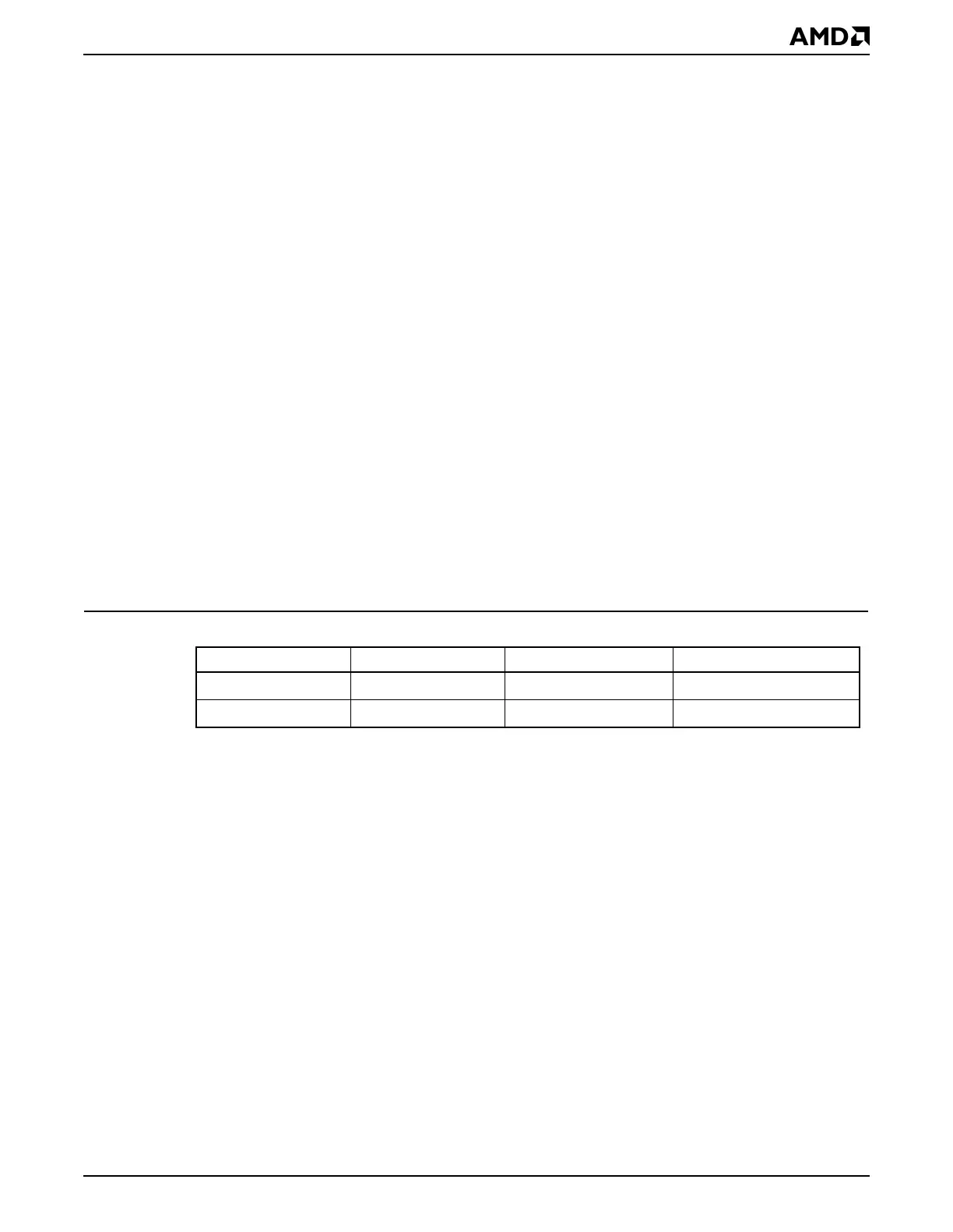
The CPUID instruction returns encodings shown in Table 3-1.
3.4 SETTING THE CPU SPEED
The ÉlanSC520 microcontroller is available at multiple clock speeds. By default, the
ÉlanSC520 microcontroller core comes up from a system reset running at 100 MHz. See
Chapter 7, “Am5x86® CPU”, for more information.
Note: Not all ÉlanSC520 microcontroller devices support all Am5
x
86 CPU clock rates. The
maximum supported clock rate for a device is indicated by the part number printed on the
package. The clocking circuitry can be programmed to run the device at higher than rated
speeds. However, if an ÉlanSC520 microcontroller is programmed to run at a higher clock
speed than that for which it is rated, then erroneous operation will result, and physical
damage to the device may occur.
3.5 CONFIGURING EXTERNAL GP BUS DEVICES
Programming the ÉlanSC520 microcontroller to support external peripherals on the GP
bus requires three steps.
1. Program the GP bus timing mechanism to control the bus timings for the device. This
is done first so that the initial access to the device (after the chip selects and PARs are
programmed) will function properly. The GP bus timings and bus cycles are discussed
in “Bus Cycles” on page 13-16.
Table 3-1 CPUID Codes
CPU Clock Speed Write-Back Mode Write-Through Mode
Am5
x
86 CPU
100 MHz
0494h 0484h
Am5
x
86 CPU
133 MHz
04F4h 04E4h