UART Serial Ports
Élan™SC520 Microcontroller User’s Manual 21-9
If receiver line status interrupts are enabled, any of the OE, PE, FE, or BI conditions trigger
an interrupt. Note that the ERR_IN_FIFO cannot directly generate an interrupt.
21.5.4 Configuration Information
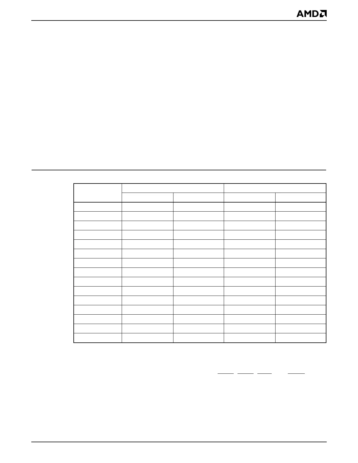
21.5.4.1 Baud Rate
To generate the baud rate of the transfer, the UART clock is divided by a divisor value
chosen by the programmer. The UART’s baud-rate generator automatically calculates the
baud rate from the divisor value programmed into the two UART x Baud Clock Divisor Latch
MSB and LSB registers. These registers are read at initialization to set the baud rate for
the transfer. The baud rate is calculated according to the following equation:
Baudrate = clockfrequency / 16 * BAUDDIV
Here, clock frequency refers to the frequency of the main reference clock, 1.8432 MHz or
18.432 MHz. This frequency is determined by the CLKSRC bit in the UART x General
Control (UARTxCTL) register. BAUDDIV is defined by the UART x Baud Clock Divisor Latch
MSB and LSB registers. Table 21-5 lists the divisor value (in decimal and hexadecimal) to
use with each clock frequency to achieve common baud rates.
21.5.4.2 Hardware Flow Control
When the EMSI bit of the UART x Interrupt Enable (UARTxINTENB) register is set, the
modem status interrupt is enabled to facilitate the hardware flow control. The interrupts are
triggered by changes in the following control lines: CTSx
, DTRx, RINx, and DCDx.
21.5.4.3 Operating Modes
16450-compatible UART mode and 16550-compatible UART mode can be setup by setting
or clearing the FIFO_ENB bit of UART x FIFO Control (UARTxFCR) register. The
ÉlanSC520 microcontroller UARTs can be switched between the 16550-compatible mode
and 16450-compatible mode under software control.
Table 21-5 Baud Rates, Divisors, and Clock Source
Baud Rate
DIV[15–0] (Decimal) DIV[15–0] (Hexadecimal)
1.8432 MHz 18.432 MHz 1.8432 MHz 18.432 MHz
300 baud 384d 3840d 0180h 0F00h
600 baud 192d 1920d 00C0h 0780h
2400 baud 48d 480d 0030h 01E0h
4800 baud 24d 240d 0018h 00F0h
7200 baud 16d 160d 000Fh 00A0h
9600 baud 12d 120d 000Ch 0078h
14.4 kbaud 8d 80d 0008h 0050h
19.2 kbaud 6d 60d 0006h 003Ch
57.6 kbaud 2d 20d 0002h 0014h
115.2 kbaud 1d 10d 0001h 000Ah
144 kbaud 8d 0008h
192 kbaud 6d 0006h
288 kbaud 4d 0004h
576 kbaud 2d 0002h
1.152 Mbaud 1d 0001h