AMDebug™ Technology
26-4 Élan™SC520 Microcontroller User’s Manual
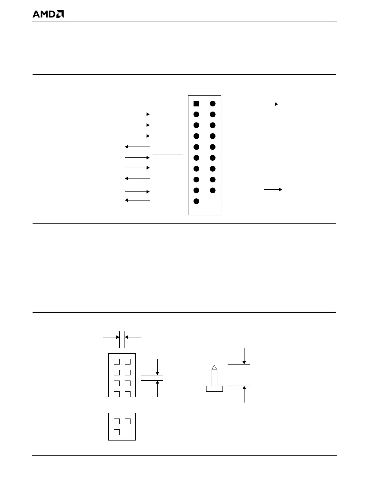
When the serial connector is clocked at high speeds, e.g., above 10 MHz, there is danger
of signal cross talk. To alleviate this problem, a 20-pin serial connector format is also
available, as shown in Figure 26-3. The arrangement places a ground wire between each
signal wire. Low-cost tools based on AMDebug technology operate satisfactorily with the
12-pin connector shown in Figure 26-2, as long as cable lengths are not too long.
Figure 26-3 20-Pin Serial Connector Format
26.3.2 Mechanical Specifications for the Target Connector
A target board should contain a connector with male header pins. Pin spacing is 2 mm for
both 12-pin and 20-pin formats, as shown in Figure 26-4. Debugging equipment should
support a ribbon cable equipped with a female connector for attaching to the target. The
appropriate last pin, pin 12 or pin 20, should not be installed, or, if necessary, removed at
this location. At this location the female connector on the ribbon cable is populated with a
post, which prevents the connector’s insertion in the reverse position. Compatible connec-
tors are available from Samtec, Inc. (model TMM-112-02-x-D for 12-pin), 3M, and other
companies.
Figure 26-4 Mechanical Specifications for AMDebug™ Technology Target Connector
Ground
Test Clock
Test Mode Select
Test Data In
Test Data Out
Reserved for
System Reset
Sample Power Source
Trigger Event
Gnd
JTAG_TCK
JTAG_TMS
JTAG_TDI
JTAG_TDO
JTAG_TRST
PWRGOOD
Gnd
Gnd
Gnd
Gnd
Keyed
12
20
SYSRESET
CMDACK
BR/TC
STOP/TX
Gnd
Gnd
Gnd
TRIG/TRACE
19
Test Reset
Command Acknowledge
Enter AMDebug Mode, Trace Control
In AMDebug Mode, Receive Data
Male connector
on target board
2 mm
2 mm
Key
Side View
3.7 mm