System Initialization
3-16 Élan™SC520 Microcontroller User’s Manual
PAR programming is required to support this configuration. Note that the internal I/O devices
will still be correctly accessed when the IO_HOLES_DEST bit is set.
However, if any external GP bus device requires I/O addresses, then a PAR register will
be required to allow access to this device. As an example, assume an external 16550 UART
is used to implement a COM3 port.
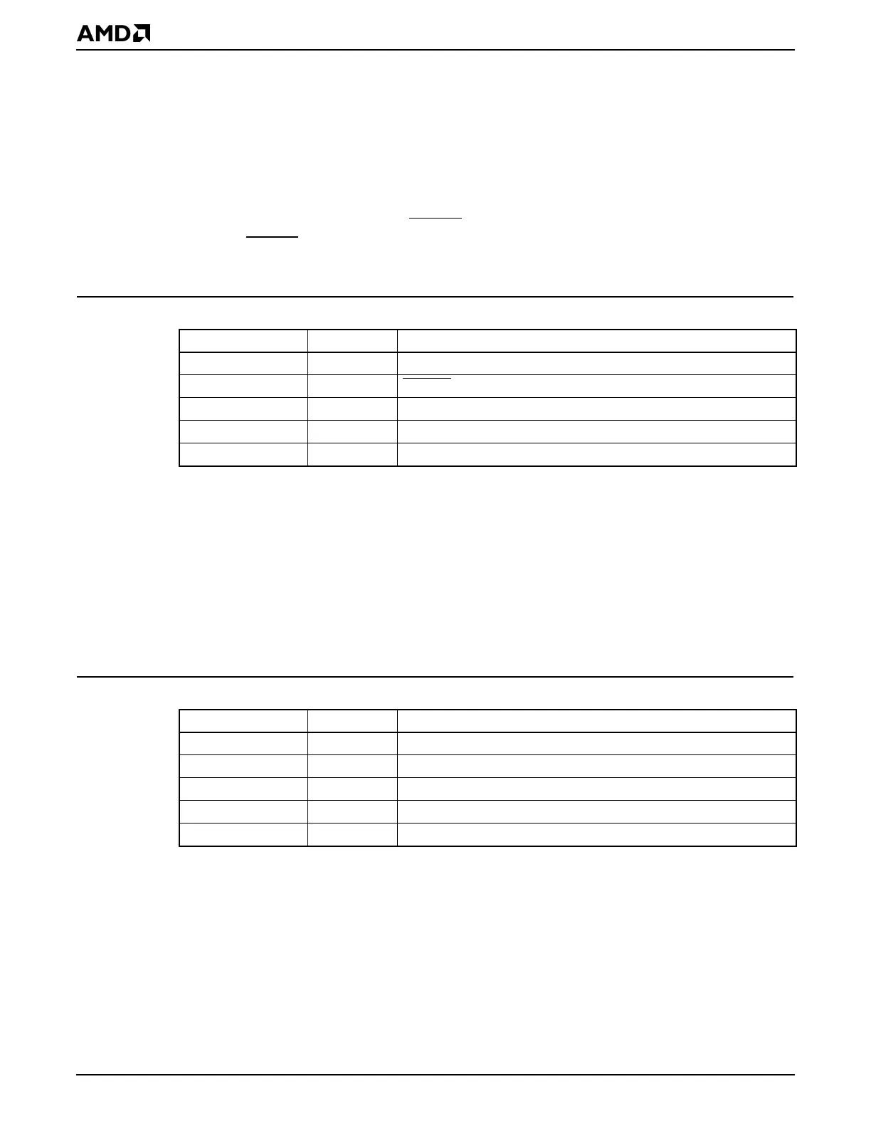
The standard I/O locations for COM3 are 03E8–03EFh. As shown in Table 3-6, a PAR
register will be required with a setting of 340703E8hto enable external GP bus accesses
to this I/O range. In this example, GPCS5
is used as a chip enable for the external device.
If another GPCS
x is required, then appropriate changes should be made to the PAR register
setting.
3.7.5.2 Network Adapter for Remote Program Loading
A memory-mapped network adapter will usually reside in PCI space that is far above the
real-mode address limit. However, to perform Remote Program Loading (RPL), often called
network boot, over a network, the 16-bit BIOS needs to use the network adapter. To avoid
writing 32-bit protected-mode BIOS code, PAR 0 or PAR 1 can be used to place a memory-
mapped network adapter above the real-mode address limit. For this example, it is assumed
that the network adapter has 16 Kbytes of address space that needs to be placed at
000B0000h. This area is noncacheable because it is PCI address space. As shown in
Table 3-7, the value to configure PAR 0 or PAR 1 for this configuration is 600C00B0h.
Note that most network adapters will also require a small amount of PCI I/O space. The
location of this I/O space can usually be changed through a PCI configuration register on
the adapter and can be assigned by an operating system through plug and play functionality.
Usually, this address can be set to any value and is typically above the 1-Kbyte I/O boundary
affected by the IO_HOLES_DEST bit. Since I/O accesses above 400h are always sent to
PCI space (unless overridden by a PAR register to go to the
GP bus), no special
programming is needed to allow I/O accesses for a typical PCI network adapter.
Table 3-6 Example PAR Programming: COM3 with VGA Present on the PCI Bus
Bit Field Value Meaning
Target Device 001b GP bus I/O space
Attribute Field 101b GPCS5
Page Size 0b Clear to 0 (this bit not applicable to I/O space)
Region Size 7h Specifies an 8-byte region size
Start Address 03E8h Physical address 03E8h
Table 3-7 Example PAR Programming: Network Adapter for Remote Program Loading
Bit Field Value Meaning
Target Device 011b PCI bus
Attribute Field 000b Not applicable
Page Size 0b 4-Kbyte granularity
Region Size 03h Specifies four 4-Kbyte pages for a 16-Kbyte region size
Start Address B0h Physical address 000B0000h