AMDebug™ Technology
26-2 Élan™SC520 Microcontroller User’s Manual
26.2 BLOCK DIAGRAM
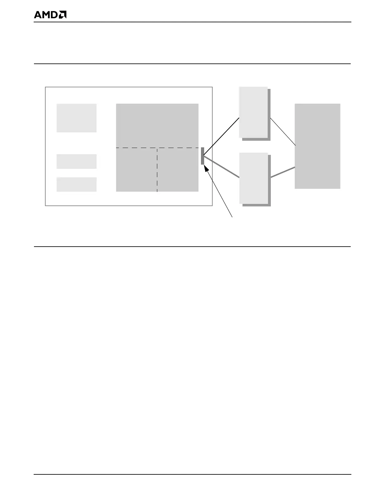
Figure 26-1 shows a system diagram of AMDebug software architecture. Two different
configurations are shown.
Figure 26-1 AMDebug™ Technology Software Architecture
26.3 SYSTEM DESIGN
The pinstrap functions associated with the GPA25–GPA23 pins, DEBUG_ENTER,
INST_TRCE, and AMDEBUG_DIS, are sampled only as a result of PWRGOOD assertion
and do not affect the GP bus functions of these pins.
26.3.1 Connecting the AMDebug™ Port
There are multiple ways of connecting the host computer to the ÉlanSC520 microcontroller’s
AMDebug port, including through a host computer’s serial port, parallel port, or via an
Ethernet connection. For specific tool and connection types, refer to AMD FusionE86 part-
ners documentation on p. iii under Third-Party Support.
At a minimum, AMDebug operation can be achieved with the four basic JTAG signal pins:
JTAG_TCK, JTAG_TMS, JTAG_TDI, and JTAG_TDO. Using JTAG pins alone, without the
advantages of additional support pins, the lowest possible cost is achieved in terms of
processor pins, but with the cost of reduced functionality. No attempt is made to multiplex
the function of the JTAG pins. Multiplexing would prevent ensuring their availability for
communication with the processor at all times and under any operating condition.
An inexpensive connector that links the PC port to the AMDebug port can be acquired to
satisfy the requirement of a large number of software developers. Connection to a target
via this simple arrangement offers considerable advantages:
■ There is no need to remove the processor to connect an in-circuit emulator-like umbilical.
■ Connection is ensured no matter what the processor packaging technology.
■ Debug communication is independent of processor or memory system clocking speeds.
Target System
eODQ6&
0LFURFRQWUROOHU
&38
RAM
UART
Trace
Cache
6HULDO3RUW3LQ&RQQHFWRURU
/RZ&RVW
6HULDO
&RQYHUWHU
+RVW6\VWHP
3&
'HEXJ
&RQWURO
6RIWZDUH
25
3DUDOOHO3RUW3LQ%RQG2XW
$0'HEXJ
/RJLF
520
7UDFH
&DSWXUH
3OXV
3DUDOOHO
,QWHUIDFH