UART Serial Ports
Élan™SC520 Microcontroller User’s Manual 21-11
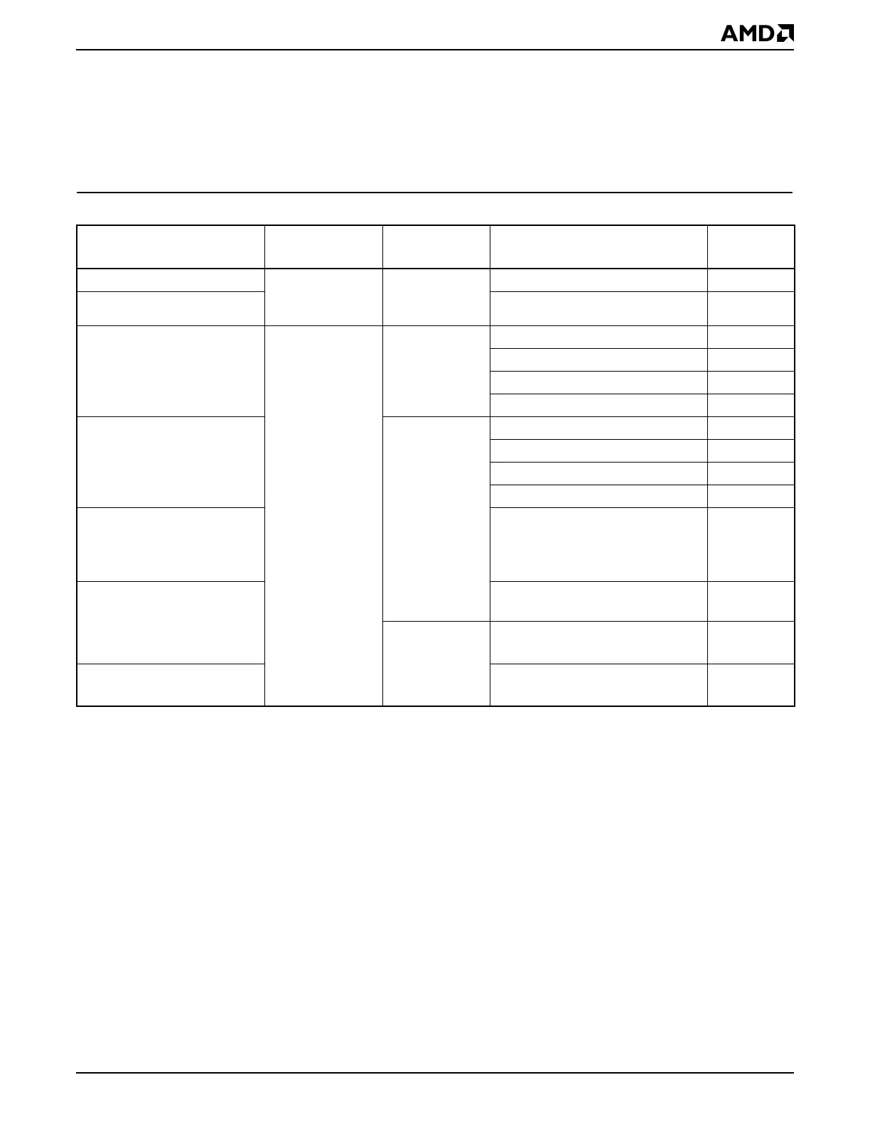
Table 21-6 provides a summary of UART interrupt sources for both DMA and serial port
interrupts.
Interrupts generated by the UARTs are cleared in a variety of ways, depending on the
source event. For details about clearing a particular event, see the event’s status bit
description in the
Élan™SC520 Microcontroller Register Set Manual
, order #22005.
Table 21-6 UART Interrupt Programming Summary
Interrupt Description
Enable
Register
1,
2
Notes:
1. Before any UART interrupt is enabled, the corresponding UART x Interrupt Mapping (UARTxMAP) register must
be configured to route the interrupt to the appropriate interrupt request level and priority.
2. The OUT2 bit in the UART x Modem Control (UARTxMCR) register is used as a master control for UART inter-
rupts. The OUT2 bit must be set for UART interrupts to be generated. Status bits can be read even when interrupts
are disabled.
Status
Register
3
3. If two of the interrupts enabled in the UART x Interrupt Enable (UARTxINTENB) register are pending simulta-
neously, the highest-priority interrupt is identified in the INT_ID bit field of the UART x Interrupt ID (UARTxINTID)
register.
Source Event
Polled
Status Bit
Receive DMA transfer count UART x General
Control
(UARTxCTL)
UART x
General Status
(UARTxSTA)
UART x Receive TC Detected RXTC_DET
Transmit DMA transfer count UART x Transmit TC Detected TXTC_DET
Modem status change UART x Interrupt
Enable
(UARTxINTENB)
UART x
Modem Status
(UARTxMSR)
Delta data carrier detect DDCD
Trailing edge ring indicator TERI
Delta data set ready DDSR
Delta clear to send DCTS
Receiver line status UART x Line
Status
(UARTxLSR)
Break indicator BI
Framing error FE
Parity error PE
Overrun error OE
Transmitter holding register
empty
Transmit holding register (16450-
compatible mode) or transmitter
FIFO (16550-compatible mode)
empty
THRE
Received data available Data ready
(16450-compatible mode)
DR
—
4
4. There are no polled-status bits for the FIFO trigger level and FIFO time-out events. These events are indicated
by the INT_ID bit field only.
FIFO trigger level reached
(16550-compatible mode)
—
FIFO time-out
5
5. The FIFO time-out interrupt is enabled with the received data available interrupt by the ERDAI bit in the UART x
Interrupt Enable (UARTxINTENB) register.
FIFO time-out
(16550-compatible mode)
—