GP Bus DMA Controller
14-10 Élan™SC520 Microcontroller User’s Manual
■ For a write transfer, the external I/O device asserts its request, waits for the acknowledge,
and places the data on the GPD bus when the I/O command (GPIORD
) is asserted.
14.5.1.1.3 External Memory-Mapped I/O Devices
An external device on the GP bus can be mapped into memory address space. See
Chapter 4, “System Address Mapping”, for more details. Such devices are referred to as
memory-mapped I/O devices
. GP-DMA transactions to a memory-mapped I/O device are
handled in the same fashion as those to an I/O device, except that the commands used
are GPMEMRD
and GPMEMWR, instead of GPIORD and GPIOWR. The GP-DMA
Memory-Mapped I/O (GPDMAMMIO) register (MMCR offset D81h) is used for this purpose.
14.5.1.2 GP-DMA Channel Mapping
GP-DMA requests can originate from the following sources:
■ Transmit and receive channels from each of two internal UART serial ports (always
8-bit) for a total of four requests
■ GP bus using GPDRQ3–GPDRQ0 and GPDACK3–GPDACK0 (8-bit or 16-bit).
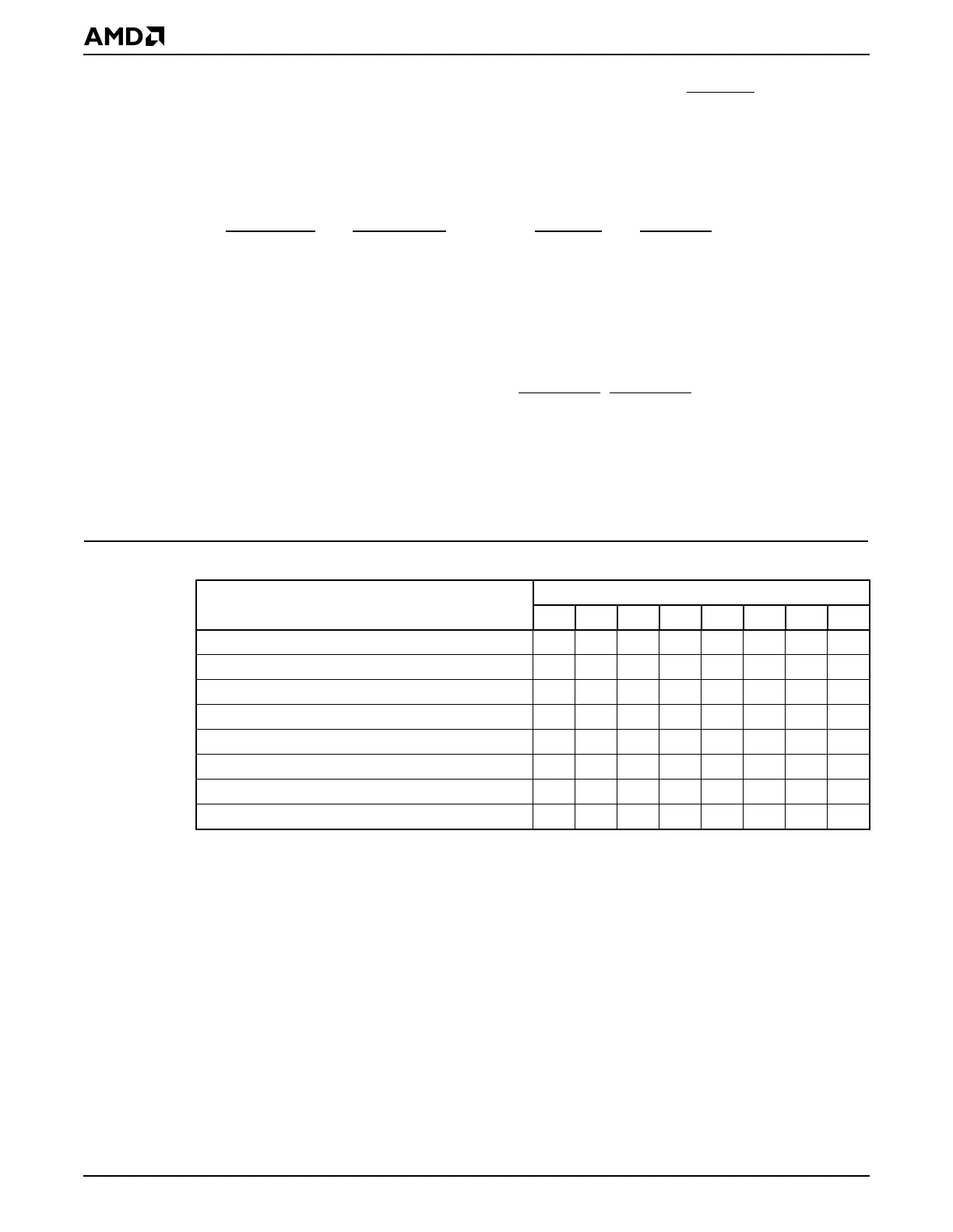
Table 14-5 shows the ÉlanSC520 microcontroller resource and the GP-DMA channels to
which the resource can be mapped.
All GP-DMA channel mapping in the ÉlanSC520 microcontroller is programmable using
the two GP-DMA Resource Channel Map x (GPDMAEXTCHMAPx) registers.
14.5.2 Operating Modes
The operating mode for the GP-DMA controller is configured using the ENH_MODE_ENB
bit in the GP-DMA Control (GPDMACTL) register (MMCR offset D80h).
14.5.2.1 Normal GP-DMA Mode
Normal GP-DMA mode is the default operating mode of the GP-DMA controller. In this
mode:
■ Channels 0, 1, 2, and 3 are used for the internal UART serial ports and external 8-bit
devices.
■ Channel 5, 6, and 7 are used for any external 16-bit devices.
This mode is compatible with the PC/AT architecture.
Table 14-5 GP-DMA Channel Mapping
Microcontroller Resource
GP-DMA Channel
01234567
UART 1 transmit request ✔✔✔✔
UART 2 receive request ✔✔✔✔
UART 1 transmit request ✔✔✔✔
UART 2 receive request ✔✔✔✔
External request GPDRQ0 ✔✔✔✔ ✔✔✔
External request GPDRQ1 ✔✔✔✔ ✔✔✔
External request GPDRQ2 ✔✔✔✔ ✔✔✔
External request GPDRQ3 ✔✔✔✔ ✔✔✔