GP Bus DMA Controller
14-6 Élan™SC520 Microcontroller User’s Manual
14.4.2 Direct-Mapped Registers
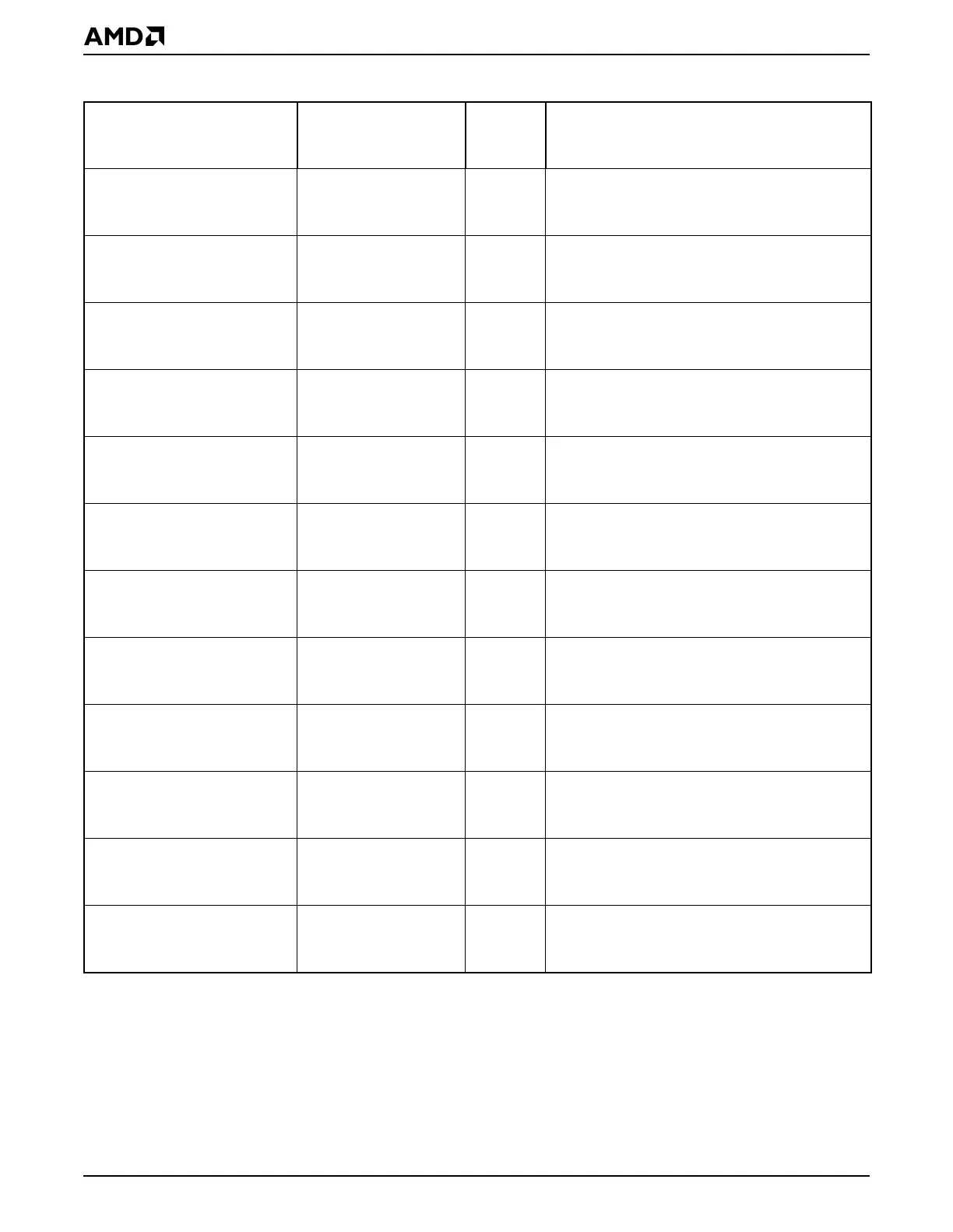
There are seven DMA channels in the GP-DMA controller. Table 14-3 shows the direct-
mapped I/O registers that are available for each of the seven channels.
There are two DMA cores in the GP-DMA controller that are cascaded to provide the seven
DMA channels. The cores are referred to as
master
and
slave
. Table 14-3 includes the set
of the direct-mapped registers available in each of two cores. These registers program the
function of the master or slave core.
GP-DMA Channel 6 Next
Address Low
GPDMANXTADDL6 DA8h Address bits 0–15 of the next data buffer in
memory used with Channel 6
(enhanced GP-DMA mode)
GP-DMA Channel 6 Next
Address High
GPDMANXTADDH6 DAAh Address bits 16–27 of the next data buffer in
memory used with Channel 6
(enhanced GP-DMA mode)
GP-DMA Channel 7 Next
Address Low
GPDMANXTADDL7 DACh Address bits 0–15 of the next data buffer in
memory used with Channel 7
(enhanced GP-DMA mode)
GP-DMA Channel 7 Next
Address High
GPDMANXTADDH7 DAEh Address bits 16–27 of the next data buffer in
memory used with Channel 7
(enhanced GP-DMA mode)
GP-DMA Channel 3 Next
Transfer Count Low
GPDMANXTTCL3 DB0h Bits 0–15 of the next transfer count for Channel
3 when using buffer chaining
(enhanced GP-DMA mode)
GP-DMA Channel 3 Next
Transfer Count High
GPDMANXTTCH3 DB2h Bits 16–23 of the next transfer count for
Channel 3 when using buffer chaining
(enhanced GP-DMA mode)
GP-DMA Channel 5 Next
Transfer Count Low
GPDMANXTTCL5 DB4h Bits 0–15 of the next transfer count for Channel
5 when using buffer chaining
(enhanced GP-DMA mode)
GP-DMA Channel 5 Next
Transfer Count High
GPDMANXTTCH5 DB6h Bits 16–23 of the next transfer count for
Channel 5 when using buffer chaining
(enhanced GP-DMA mode)
GP-DMA Channel 6 Next
Transfer Count Low
GPDMANXTTCL6 DB8h Bits 0–15 of the next transfer count for Channel
6 when using buffer chaining
(enhanced GP-DMA mode)
GP-DMA Channel 6 Next
Transfer Count High
GPDMANXTTCH6 DBAh Bits 16–23 of the next transfer count for
Channel 6 when using buffer chaining
(enhanced GP-DMA mode)
GP-DMA Channel 7 Next
Transfer Count Low
GPDMANXTTCL7 DBCh Bits 0–15 of the next transfer count for Channel
7 when using buffer chaining
(enhanced GP-DMA mode)
GP-DMA Channel 7 Next
Transfer Count High
GPDMANXTTCH7 DBEh Bits 16–23 of the next transfer count for
Channel 7 when using buffer chaining
(enhanced GP-DMA mode)
Table 14-2 GP-DMA Controller Registers—Memory-Mapped (Continued)
Register Mnemonic
MMCR
Offset
Address Function