GP Bus DMA Controller
Élan™SC520 Microcontroller User’s Manual 14-5
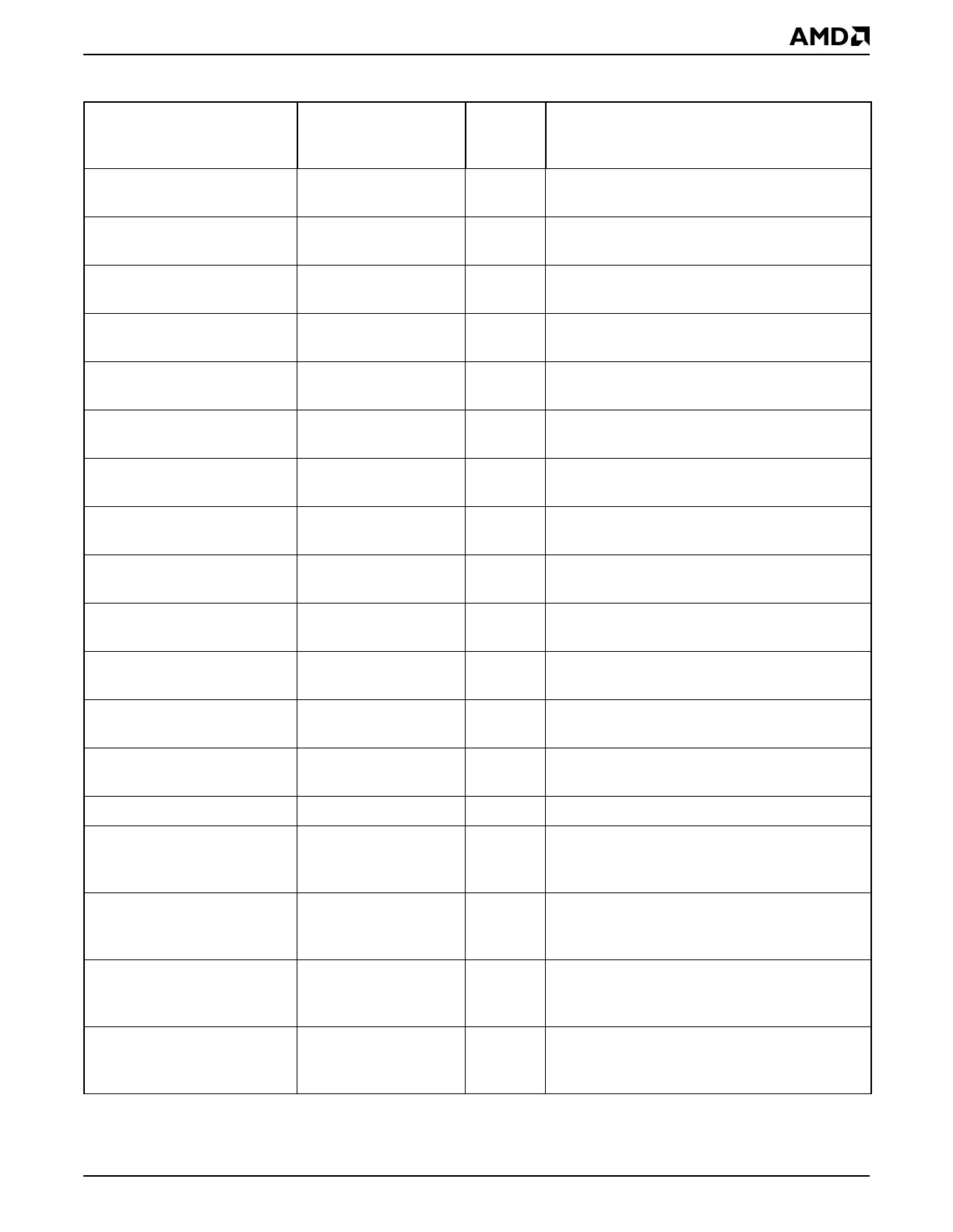
GP-DMA Channel 1
Extended Page
GPDMAEXTPG1 D87h Bits 27–24 of the memory address for
Channel 1
GP-DMA Channel 2
Extended Page
GPDMAEXTPG2 D88h Bits 27–24 of the memory address for
Channel 2
GP-DMA Channel 3
Extended Page
GPDMAEXTPG3 D89h Bits 27–24 of the memory address for
Channel 3
GP-DMA Channel 5
Extended Page
GPDMAEXTPG5 D8Ah Bits 27–24 of the memory address for
Channel 5
GP-DMA Channel 6
Extended Page
GPDMAEXTPG6 D8Bh Bits 27–24 of the memory address for
Channel 6
GP-DMA Channel 7
Extended Page
GPDMAEXTPG7 D8Ch Bits 27–24 of the memory address for
Channel 7
GP-DMA Channel 3
Extended Transfer Count
GPDMAEXTTC3 D90h Bits 23–16 of Channel 3 transfer count value
(enhanced GP-DMA mode)
GP-DMA Channel 5
Extended Transfer Count
GPDMAEXTTC5 D91h Bits 23–16 of Channel 5 transfer count value
(enhanced GP-DMA mode)
GP-DMA Channel 6
Extended Transfer Count
GPDMAEXTTC6 D92h Bits 23–16 of Channel 6 transfer count value
(enhanced GP-DMA mode)
GP-DMA Channel 7
Extended Transfer Count
GPDMAEXTTC7 D93h Bits 23–16 of Channel 7 transfer count value
(enhanced GP-DMA mode)
Buffer Chaining Control GPDMABCCTL D98h Buffer chaining enables for channels 7, 6, 5,
and 3
Buffer Chaining Status GPDMABCSTA D99h Buffer chaining status for channels 7, 6, 5, and
3
Buffer Chaining Interrupt
Enable
GPDMABSINTENB D9Ah Buffer chaining interrupt enables for channels
7, 6, 5, and 3
Buffer Chaining Valid GPDMABCVAL D9Bh Valid buffer of the buffer chaining operation
GP-DMA Channel 3 Next
Address Low
GPDMANXTADDL3 DA0h Address bits 0–15 of the next data buffer in
memory used with Channel 3
(enhanced GP-DMA mode)
GP-DMA Channel 3 Next
Address High
GPDMANXTADDH3 DA2h Address bits 16–27 of the next data buffer in
memory used with Channel 3
(enhanced GP-DMA mode)
GP-DMA Channel 5 Next
Address Low
GPDMANXTADDL5 DA4h Address bits 0–15 of the next data buffer in
memory used with Channel 5
(enhanced GP-DMA mode)
GP-DMA Channel 5 Next
Address High
GPDMANXTADDH5 DA6h Address bits 16–27 of the next data buffer in
memory used with Channel 5
(enhanced GP-DMA mode)
Table 14-2 GP-DMA Controller Registers—Memory-Mapped (Continued)
Register Mnemonic
MMCR
Offset
Address Function