Real-Time Clock
Élan™SC520 Microcontroller User’s Manual 20-3
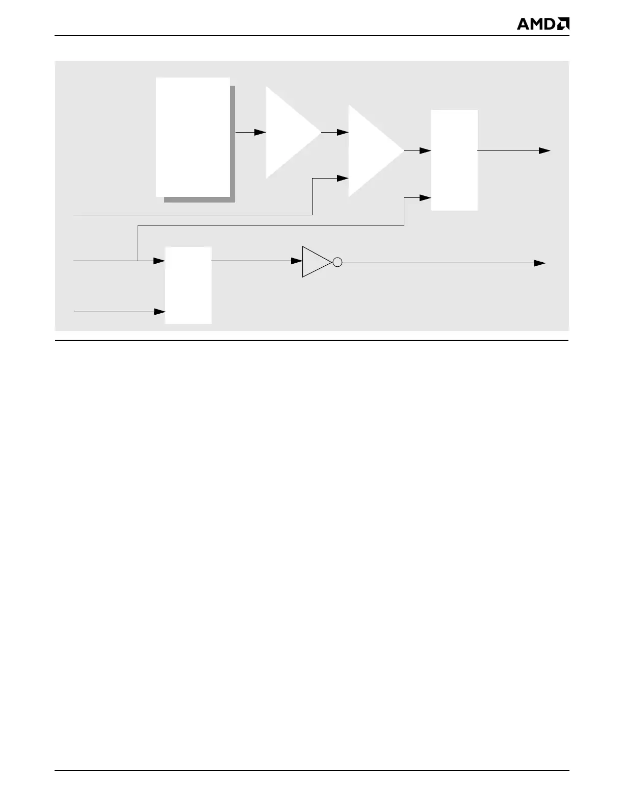
Figure 20-2 RTC Voltage Monitor Block Diagram
20.3 SYSTEM DESIGN
20.3.1 Backup Battery Considerations
The behavior of the RTC when the primary power supply is turned off depends on whether
or not an external backup battery is included in the system design. The RTC can be
connected to the main power plane if a backup battery is not needed in the system.
20.3.1.1 System with an External Backup Battery
If an external RTC backup battery is connected to the ÉlanSC520 microcontroller’s
VCC_RTC pin, the real-time clock (RTC) remains operational even if all the other power
supplies are turned off.
An implementation using a backup battery is shown in Figure 20-3. The primary power
source for VCC_RTC is the main power plane (V
CC
). D1 should be chosen so that the
forward voltage drop is small, less than 0.25 V. D1 also prevents the backup battery from
powering up the V
CC
power plane when the main supply is turned off.
The backup battery voltage must not exceed 3.3 V (affects the BBATSEN and VCC_RTC
pins); higher voltages may damage the ÉlanSC520 microcontroller.
The RC network composed of R1 and C2 provides a time delay for the internal circuit power-
up sequence. C1 is for high-frequency filtering purposes.
See the
Élan™SC520 Microcontroller Data Sheet
, order #22003, for detailed component
specifications.
+
–
Bandgap
VBG
Amplifier
BBATSEN
One
Shot
RTC Reset
Flip-
Flop
D
CK
Q
PWRGOOD
32 kHz
Internal RTC Power-Down
2.0 V
Voltage
Generator