Reset Generation
6-2 Élan™SC520 Microcontroller User’s Manual
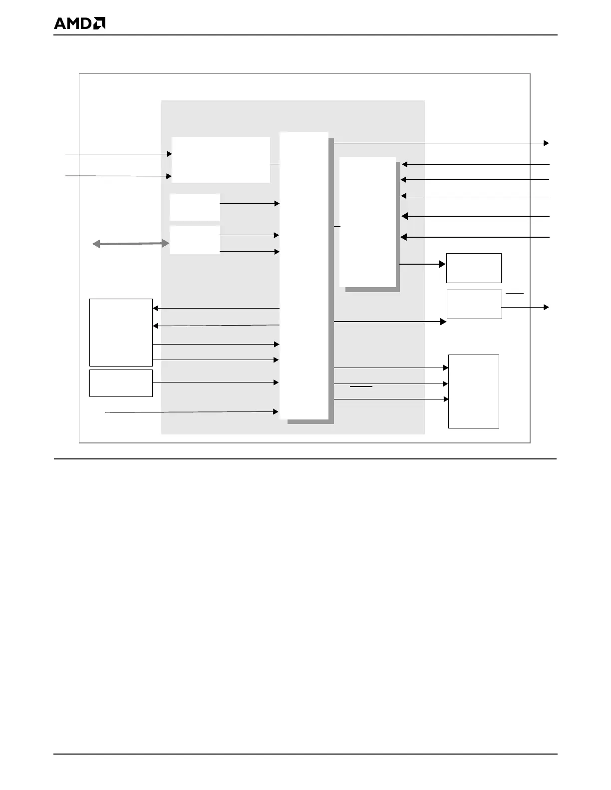
Figure 6-1 Reset Controller Block Diagram
6.3 SYSTEM DESIGN
The POWERGOOD signal from the system board is connected to the PWRGOOD pin on
the ÉlanSC520 microcontroller to produce CPU reset and system reset events. During the
period required for stabilization of the power supplies and the internal oscillators, which is
typically not less than 1 second, the POWERGOOD signal is kept deasserted. The start-
up time of the internal PLLs is typically 10 ms from the assertion of the PWRGOOD pin.
The power-on reset waveform diagram is shown in Figure 6-3 on page 6-9.
All system resets, aside from PWRGOOD pin, are on the order of 10 ms, while soft resets
take 16 CPU clocks.
See the
Élan™SC520 Microcontroller Data Sheet
, order #22003, for timing tables and
additional timing diagrams.
Port A
cpu sreset
port92_rst
shutdown
PRGRESET
PWRGOOD
Watchdog
wdt_rst
cpu reset
GP Bus
a20m
CFG3–CFG0
AMDebug system reset
RSTLD7–RSTLD0
AMDebug hard reset
Reset Configuration
Register
Pinstrap
Status
GPRESET
AMDebug on reset
rst_main
AMDebug™
and
Information
To all internal
cores
PCI
Controller
RST
SCP
a20_gate
Registers
port64_rst
a20_ctl
ROM
Controller
rom
AMDEBUG_DIS
INST_TRCE
DEBUG_ENTER
AMDebug
Logic
CPU
System
Élan™SC520 Microcontroller
Timer
Reset Controller
Reset
Source
Detect
config