UART Serial Ports
Élan™SC520 Microcontroller User’s Manual 21-5
21.5 OPERATION
Each UART performs:
■
Serial-to-parallel
conversion on data characters received from a modem or a peripheral
device
■
Parallel-to-serial
conversion on those data characters written by the CPU or DMA
controller
During communication, data is transmitted and received in
frames
. The frame format, as
well as the baud rate, must be the same on the transmitter and receiver. The frame format
is determined by the settings in the UART x Line Control (UARTxLCR) register. Each frame
begins with a start bit (Low) and ends with one, one and a half, or two stop bits (High). After
the start bit is transmitted/received, the data bits, which can be programmed to a length of
5, 6, 7 or 8 bits, are transmitted/received serially with least significant bit first.The last data
bit may be followed by an optional parity bit that is enabled using the PENB bit in the UART
x Line Control (UARTxLCR) register. The line is always held High between frames (idle
state).
■
Transmission
of a frame is initiated when a byte is written to the UART x Transmit Holding
(UARTxTHR) register.
■
Reception
of a frame is initiated when a start bit is received (the SIN input is driven Low
for one baud-rate clock period).
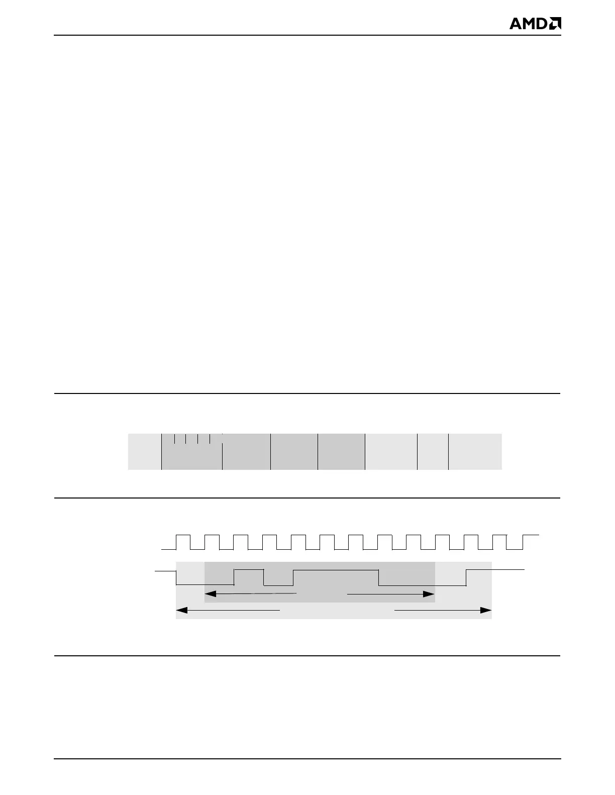
Figure 21-2 shows the frame configurations supported and the bit stream sequence for a
UART on the ÉlanSC520 microcontroller. Figure 21-3 shows an actual UART frame during
transmission with configuration of even parity, one stop bit, and eight data bits.
Figure 21-2 UART Frame Configuration
Figure 21-3 UART Frame Transmission
Each UART includes a programmable baud-rate generator that is capable of dividing the
timing reference clock input by divisors of 1 to ( ), and producing a 16 x clock for driving
the internal transmitter/receiver logic.
Start
Bit 5 Data Bits
Optional
6th
Data Bit
Optional
7th
Data Bit
Optional
8th
Data Bit
Optional
Parity Bit
Stop
Bit
Optional
0.5 or 2nd
Stop Bit
Baud Clock
TxD or RxD
idle
0
1
0
1
10
0
idle
Asynchronous transmission of 03Ah as 8 bits of data, even parity, one stop bit
1
stop
parity
start
Asynchronous serial frame
Serial data
2
16
1–