Boundary Scan Test Interface
25-20 Élan™SC520 Microcontroller User’s Manual
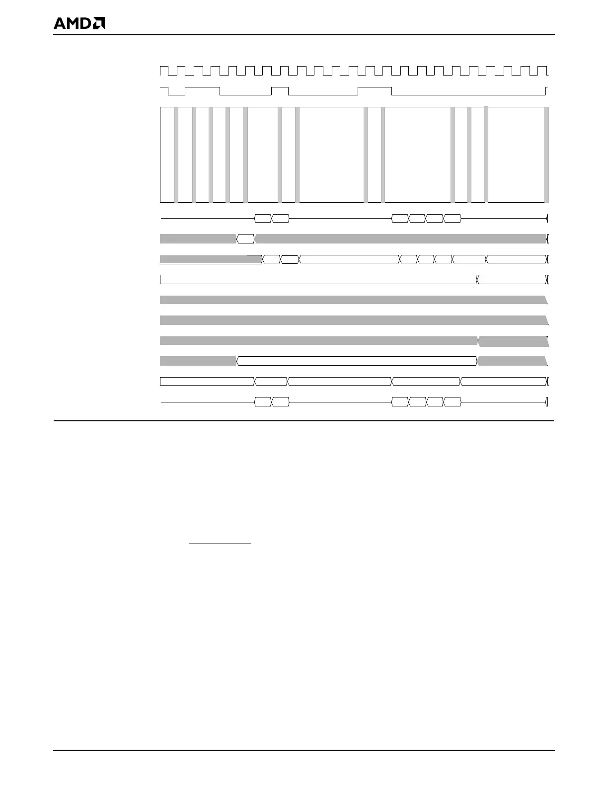
Figure 25-6 Test Logic Operation: Instruction Scan
25.4.5 Clocking Considerations
The targeted speed of operation for boundary scan is 25 MHz.
25.5 INITIALIZATION
The JTAG TAP controller is not reset as a function of PWRGOOD when the system is
powered up.
The test access port controller can be reset in the following ways:
■ When the JTAG_TRST pin is driven Low (0)—This resets the entire JTAG subsystem
including the Instruction register.
■ When the JTAG_TMS pin is held High (1) for at least five rising edges of JTAG_TCK—
It remains in this state while JTAG_TMS is High (1). If the TAP controller leaves the reset
state owing to an erroneous Low (0) signal on the JTAG_TMS line at the time of a rising
edge on JTAG_TCK, it returns to the reset state after JTAG_TMS is held High for three
rising edges of JTAG_TCK.
In the Test-Logic-Reset State of the TAP controller, the test logic is disabled so that normal
operation of the device can continue without any hindrance. See “Test-Logic-Reset State”
on page 25-15.
JTAG_TCK
JTAG_TMS
JTAG_TDI
Data Input to IR
IR Shift Register
Parallel Output of IR
Data Input to BSR
BSR Shift Register
Parallel Output of BSR
Register Selected
JTAG_TDO Enable
JTAG_TDO
Test-Logic-Reset
Run-Test/Idle
Select-DR-Scan
Select-IR-Scan
Capture-IR
Shift-IR
Exit1-IR
Pause-IR
Exit2-IR
Shift-IR
Exit1-IR
Update-IR
Run-Test/Idle
IDCODE
New Instruction
Instruction Register
Inactive
Active
Inactive
Active
Inactive
Controller State
0001