Programmable Input/Output
23-2 Élan™SC520 Microcontroller User’s Manual
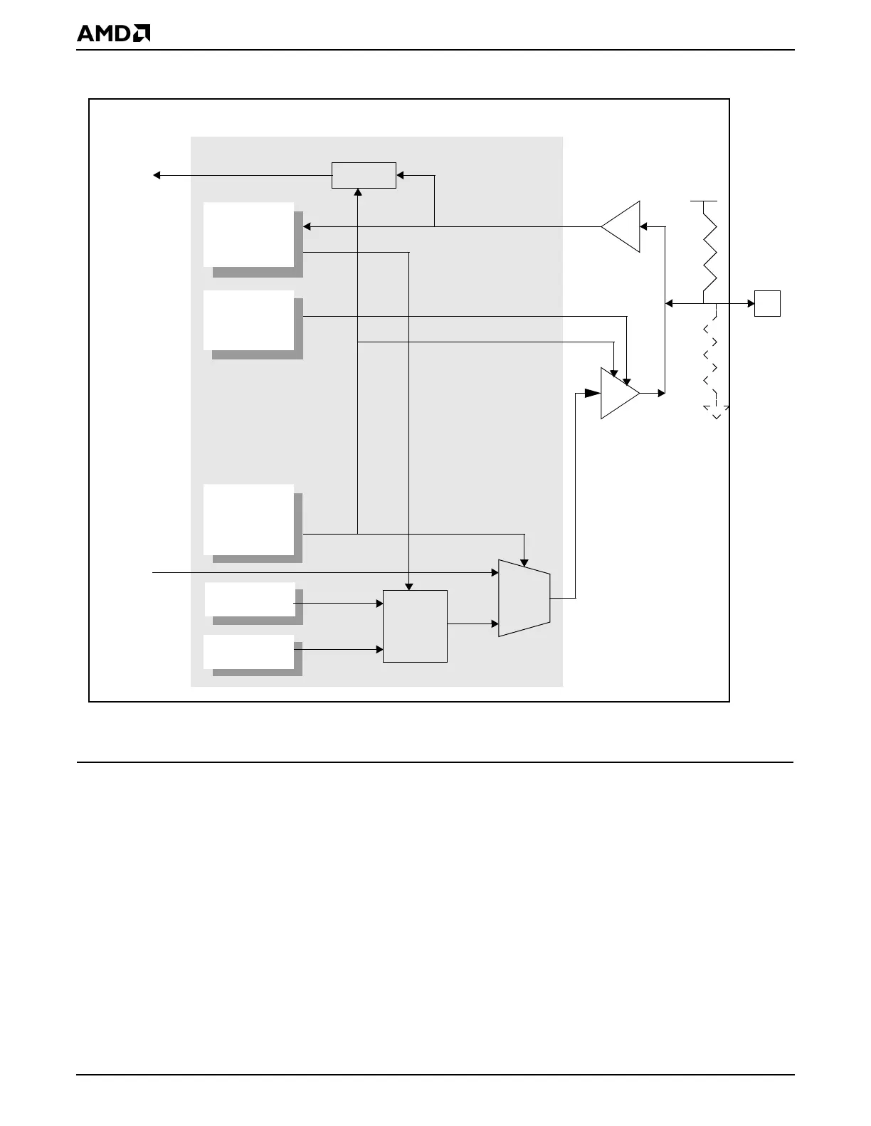
Figure 23-1 PIO Signal Block Diagram
23.3 SYSTEM DESIGN
Because most of the PIOs share pins with other functions, designers are usually constrained
in choosing which PIO pins to use in their system designs (i.e., they may need the interface
function on their board). Choosing between PIOs and interface functions is done on a PIO
basis in the two PIOx Pin Function Select registers, as shown in Table 23-1. When enabled,
the multiplexed signals shown in Table 23-1 either disable or alter any other function that
uses the same pin.
Note: All PIOs are terminated by either pullup or pulldown resistors (depending on interface
function’s needs). The pullup and pulldown resistors are approximately 100–150 ohms.
The termination of the pin should be considered when deciding which PIO to use. For
example, if a PIO that is pulled down by default is to be used for a chip select, the internal
pulldown will have to be overridden by a stronger external pullup resistor, or else the external
device will have its chip select active at reset.
PIOx
PIO
Direction
Register
PIO
Data
Register
PIO
Pin Function
Select
Register
Interface
Function
S
Interface
Function
Gate
V
CC
_IO
PIO Set
Register
PIO Clear
Register
50
–
150 K50
–
150 K
Logic
Élan™SC520 Microcontroller
Notes:
A PIO has either a pullup or pulldown resistor, but not both.