System Test and Debugging
Élan™SC520 Microcontroller User’s Manual 24-3
24.4 OPERATION
The ÉlanSC520 microcontroller provides several features that are useful in a lab
environment for system-level debugging of both hardware and software. These features
can be used in conjunction with an in-circuit emulation system, but can also be used
independently to simplify some debugging activities. Many features are expected to be
used with a logic analyzer to capture system transaction information. These distinct system-
level debugging features are described in the separate sections of this chapter.
The three-pin debugging interface is a particularly useful feature of the ÉlanSC520
microcontroller. This interface operates in two different modes:
■ System test mode
■ Write buffer test mode
24.4.1 System Test Mode
System test mode is the primary use of the three-pin interface, which enables the pins to
be monitored with a logic analyzer or external in-circuit emulation system hardware to gain
important knowledge of current Am5
x
86 CPU cycles.
System test mode is used primarily to differentiate Am5
x
86 CPU code fetches from normal
memory read cycles on the SDRAM and ROM/Flash or GP bus interface. A signal
(DATASTRB) is also provided to identify when the data on the SDRAM data bus is valid.
This signal is used primarily by in-circuit emulation tools for capturing SDRAM data when
monitoring this interface.
System test mode is enabled by clearing the WB_TST_ENB bit in the SDRAM Control
(DRCCTL) register (MMCR offset 10h). System test mode is the default test mode on the
ÉlanSC520 microcontroller. The multiplexed debugging signals then operate as described
in Section 24.4.1.1.
24.4.1.1 Pin Functions in System Test Mode
24.4.1.1.1 CF_DRAM
During SDRAM read cycles, the CF_DRAM signal provides code fetch status.
■ When Low, if DATASTRB is active in the current cycle, this signal indicates that the
current SDRAM read is a CPU code fetch demanded by the CPU, or a read prefetch
initiated due to a demand code fetch by the CPU.
■ When High, this signal indicates that the SDRAM read is not a code fetch, and it could
have been initiated by the CPU, PCI master, or the GP-DMA controller, either demand
or prefetch.
During SDRAM write cycles, the CF_DRAM
signal provides an indication of the source of
the data, either GP-DMA controller/PCI bus master, or CPU.
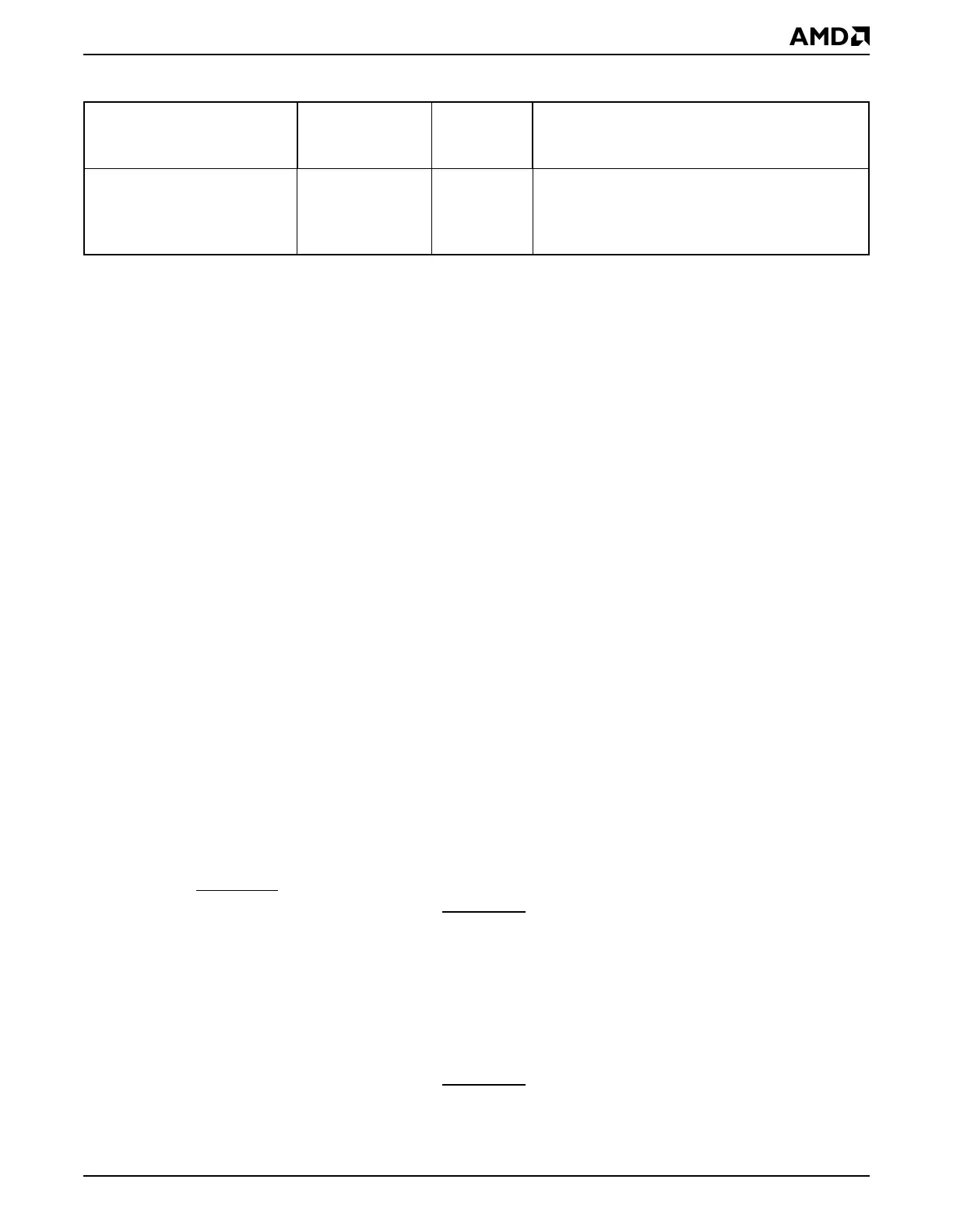
Reset Status RESSTA D74h Reset source status: SCP reset, AMDebug hard
reset detect, AMDebug system reset, watchdog
timer time-out, CPU shutdown (soft reset),
PRGRESET pin, and PWRGOOD pin
Table 24-2 System Test and Debugging Registers—Memory-Mapped (Continued)
Register Mnemonic
MMCR
Offset
Address Function