Programmable Interrupt Controller
15-12 Élan™SC520 Microcontroller User’s Manual
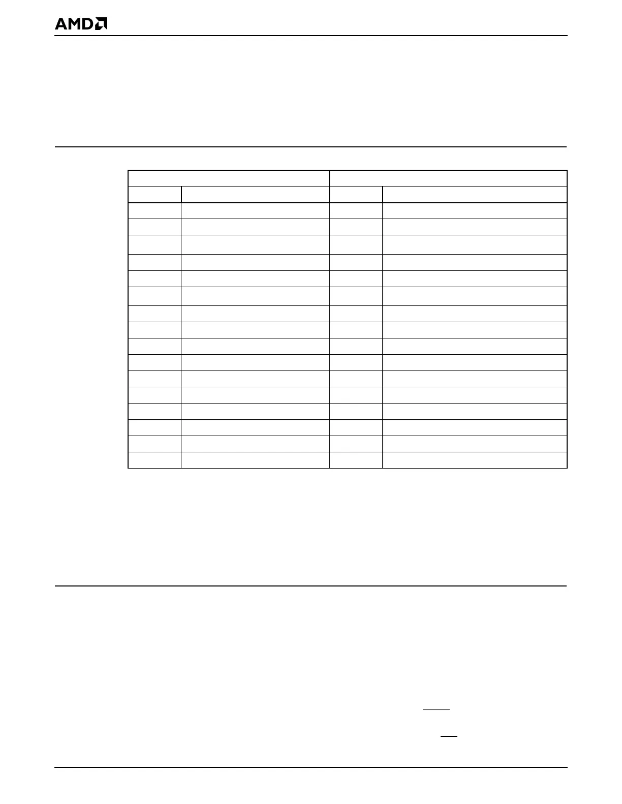
15.5.3.2 PC/AT Compatibility
For PC/AT-compatible systems, the microcontroller hardware does not automatically map
legacy ISA interrupt signals to their respective Slave 1 and Master controllers. The user’s
software must ensure that these interrupts are routed correctly to the appropriate PC/AT-
compatible channels. Table 15-4 shows the interrupt channel assignment implemented in
a PC/AT-compatible system.
15.5.3.3 Floating Point Errors
The ÉlanSC520 microcontroller supports DOS-compatible floating point error handling via
the standard Floating Point Error Interrupt Clear (FPUERRCLR) register (Port 00F0h), as
in legacy PC/AT systems. PC/AT systems control floating point error reporting externally
through the PC’s interrupt controller, rather than through the internal CPU interrupt. In this
case, an interrupt request is generated and typically routed to IRQ13 (although it is
programmable via the ÉlanSC520 microcontroller’s PIC). This allows an interrupt handler
to write to the Floating Point Error Interrupt Clear (FPUERRCLR) register to clear the
interrupt request and force the CPU’s ignore numeric error (ignne
) signal active, thus
enabling execution of floating-point instructions within the interrupt handler. Once the FPU
error condition is cleared by the handler, the floating point error (ferr
) signal is deasserted,
Table 15-4 PC/AT Interrupt Channel Mapping
PC/AT-Compatible System ÉlanSC520 Microcontroller
IRQ I/O Device Priority Interrupt Source to Map
IRQ0 System Timer 0 P1 Internal (PIT 0 interrupt)
IRQ1 Keyboard interface P2 External via GPIRQx pin
IRQ2
1, 2
Notes:
1. In the ÉlanSC520 microcontroller’s PIC, interrupt channels 2 and 5 of the Master interrupt con-
troller are hard-wired to the outputs of Slave 1 and Slave 2 interrupt controllers, respectively. The
cascading of the slave controllers is fixed in order to simplify the system interrupt programming
model.
2. When configured for PC/AT-compatible operation, the Slave 1 interrupt controller is cascaded
and the Slave 2 controller is bypassed. In this configuration, IRQ2 is not available, and interrupt pri-
ority P13 acts as IRQ5. For configuration details see “PC/AT Compatibility” on page 15-12.
Slave controller cascading
—
Cascaded from Slave 1 controller
IRQ3 UART 2 P11 Internal (UART 2 interrupt)
IRQ4 UART 1 P12 Internal (UART 1 interrupt)
IRQ5
1, 2
Parallel port 2
P13
External via GPIRQx pin
IRQ6 Floppy disk controller P21 External via GPIRQx pin
IRQ7 Parallel port 1 P22 External via GPIRQx pin
IRQ8 Real-time clock P3 Internal (RTC interrupt)
IRQ9 Any 8- or 16-bit ISA device P4 External via GPIRQx pin
IRQ10 Any 8- or 16-bit ISA device P5 External via GPIRQx pin
IRQ11 Any 8- or 16-bit ISA device P6 External via GPIRQx pin
IRQ12 Mouse interface P7 External via GPIRQx pin
IRQ13 Numeric coprocessor P8 Internal (floating point error interrupt)
IRQ14 Any 8- or 16-bit ISA device P9 External via GPIRQx pin
IRQ15 Any 8- or 16-bit ISA device P10 External via GPIRQx pin