PCI Bus Host Bridge
Élan™SC520 Microcontroller User’s Manual 9-15
delay (the arbiter is parked on the host bridge). If another external PCI bus master was
granted the bus or the bus was not idle, FRAME
assertion would be delayed until the
host bridge’s gnt
was asserted and the bus was idle.
■ Clock #14: The PCI bus target asserts TRDY indicating the data is available.
■ Clock #15: The PCI host bridge samples TRDY asserted and latches the data from the
PCI bus.
■ Clock #18: The Am5
x
86 CPU bus synchronizes the end of the PCI bus cycle and asserts
rdy
to the Am5
x
86 CPU with the requested read data.
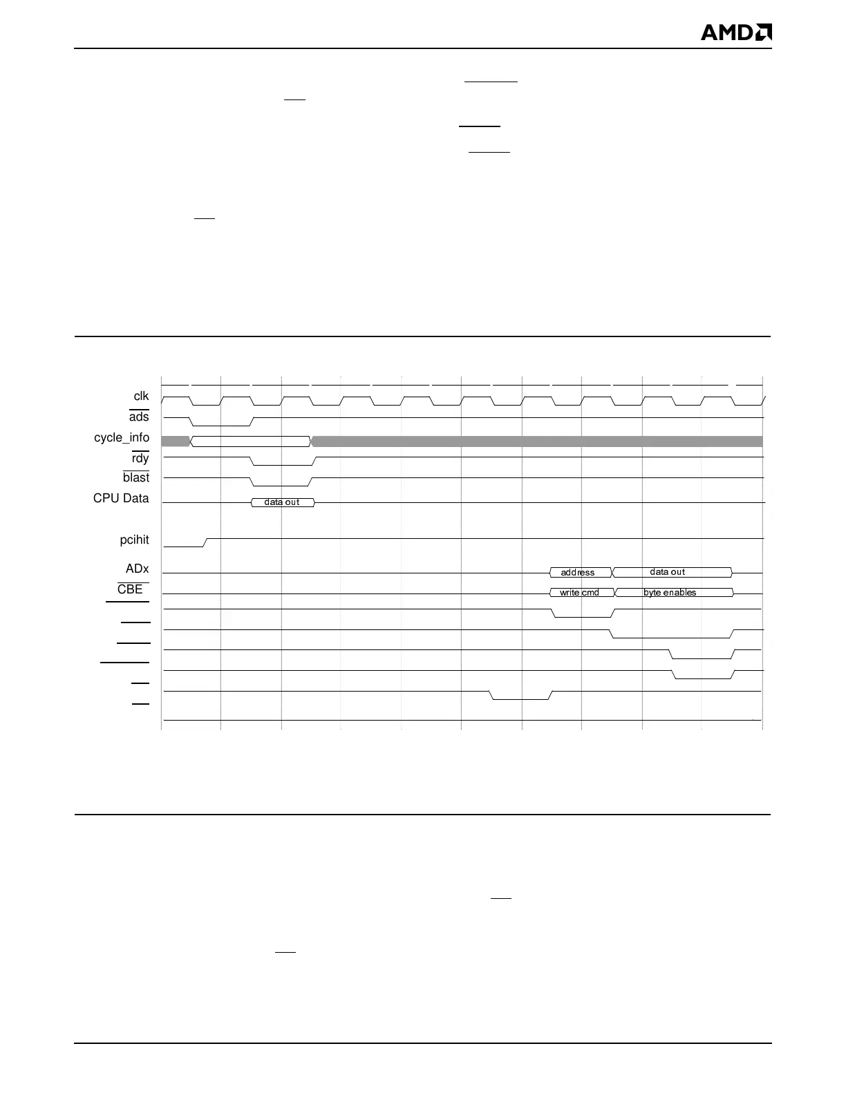
9.5.3.4.3 CPU Posted Write Cycle to the PCI Bus
Figure 9-10 shows an Am5
x
86 CPU write cycle to the PCI bus that is posted by the PCI
host bridge. This can only be a memory-write cycle to the PCI bus; I/O and configuration
writes are not posted.
Figure 9-10 CPU Posted Write Cycle to the PCI Bus
Notes:
The clk signal denotes the 33-MHz clock source and represents both the CPU clock and the PCI clock. This diagram
does not represent the full synchronization of signals between these clock domains.
The following sequence annotates the Am5
x
86 CPU posted write cycle to the PCI bus
shown in Figure 9-10.
■ Clock #1: The Am5
x
86 CPU starts a write cycle to the PCI bus.
■ Clock #2: The PCI host bridge also asserts rdy to the Am5
x
86 CPU, which ends the
Am5
x
86 CPU write cycle. The PCI bus transaction has been posted in the host bridge
and will complete sometime later. If another write cycle is already pending in the posted
write buffer, rdy
will be delayed to the Am5
x
86 CPU until the preceding posted write has
completed.
1 2 3 4 5 6 7 8 9 10
DGGUHVV
E\WHHQDEOHV
GDWDRXW
ZULWHFPG
GDWDRXW
clk
ads
cycle_info
rdy
blast
CPU Data
pcihit
ADx
CBEx
FRAME
IRDY
TRDY
DEVSEL
req
gnt