GP Bus DMA Controller
14-16 Élan™SC520 Microcontroller User’s Manual
The automatic initialization control mode cannot be used in conjunction with buffer chaining
mode.
14.5.5 Bus Cycles
Table 14-8 shows the four GP-DMA cycle types and the command strobes generated in
each cycle. The GP bus command strobes GP
MEMRD and GPMEMWR are asserted for
memory-mapped I/O devices on this bus. The internal memory commands are not shown
in this table.
14.5.5.1 GP Bus I/O to SDRAM
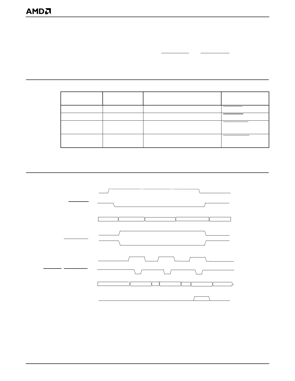
Figure 14-6 shows a GP-DMA read cycle in demand transfer mode.
Figure 14-6 GP-DMA Read in Demand Transfer Mode
Table 14-8 GP-DMA Cycle Types
GP-DMA Initiator GP-DMA Target
Data Transfer Direction
(GP-DMA Cycle Type)
GP Bus Command
Strobes Generated
I/O device SDRAM I/O to memory (GP-DMA write) GPIORD
I/O device SDRAM Memory to I/O (GP-DMA read) GPIOWR
Memory-mapped
I/O device
SDRAM Memory-Mapped I/O to memory
(GP-DMA write)
GPMEMRD
Memory-mapped
I/O device
SDRAM Memory to memory-mapped I/O
(GP-DMA read)
GPMEMWR
GPDACKx
daddr[27:0]
GPAEN
GPIOWR
, GPMEMWR
GPD15
–
GPD0
GPTC
dmemr
GPDRQx
Addr Valid
Data Valid
Data Valid
Data Valid
Addr Valid
Addr Valid
GPDBUFOE