GP Bus DMA Controller
Élan™SC520 Microcontroller User’s Manual 14-13
14.5.4.3 Block Transfer Mode
In
block transfer mode
, the GP-DMA initiator asserts GPDRQ and holds it active until
acknowledged by the assertion of GPDACK
x. The GP-DMA controller performs GP-DMA
transfers until TC is reached, indicating the programmed number of transfers has been
completed.
14.5.4.4 Transfer Types
Three GP-DMA transfer types are supported: read, write, and verify.
■ A
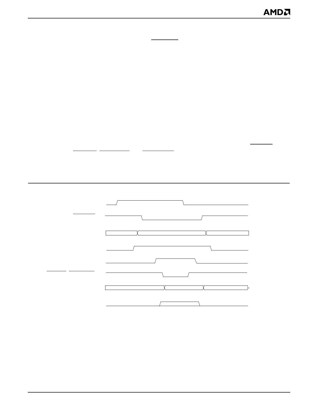
read transfer
, shown in Figure 14-3, consists of a memory read cycle from the address
in the current address register (concatenation of the channel’s Memory Address register,
Page register, and Extended Page register), followed by an I/O write cycle to the
associated device.
■ A
write transfer
, shown in Figure 14-4, consists of an I/O read cycle followed by a memory
write cycle to the address in the current address register. Depending on the GP-DMA
channel selected, the data can be 8 bits or 16 bits in width.
■ A
verify transfer
, shown in Figure 14-5, is either a read transfer or a write transfer, but
without the generation of the I/O and memory control signals, such as GPIORD
,
GPIOWR
, GPMEMRD, and GPMEMWR. A verify transfer is normally used for checking
the GP-DMA core to determine whether the address generation and control logic are
operating correctly. Data are not transferred in a verify cycle. ÉlanSC520 microcontroller
does not drive the SDRAM address out on the MA address bus during a DMA verify cycle.
Figure 14-3 GP-DMA Read Transfer
GPDACKx
daddr[27:0]
GPAEN
GPIOWR
, GPMEMWR
GPD15
–
GPD0
GPTC
dmemr
GPDRQx
Address Valid
Data Valid