PCI Bus Host Bridge
9-2 Élan™SC520 Microcontroller User’s Manual
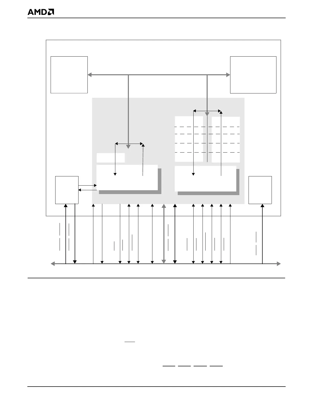
Figure 9-1 PCI Interface Block Diagram
9.3 SYSTEM DESIGN
Figure 9-2 shows how the ÉlanSC520 microcontroller can be connected to an external PCI
bus
target
device.
Figure 9-3 on page 9-4 shows how the ÉlanSC520 microcontroller can be connected to an
external PCI bus
master
device.
In each configuration, the PCI bus clock is driven from the ÉlanSC520 microcontroller on
the CLKPCIOUT pin and may require external buffering due to system loading (see “PCI
Clocking” on page 9-5). RST
, the PCI bus reset signal, is driven from the ÉlanSC520
microcontroller.
The optional PCI bus target device interrupts can be connected to the PCI bus interrupt
pins on the ÉlanSC520 microcontroller (INTA
, INTB, INTC, INTD) or any of the GPIRQ10–
PCI Host Bridge Controller
FIFO
PCI Bus
IRDY
AD31–AD0
FRAME
CBE3–CBE0
PAR
TRDY
STOP
DEVSEL
PERR
SERR
GNT4–GNT0
REQ4–REQ0
PCI
Arbiter
CLKPCIOUT
RST
INTA–INTD
CLKPCIIN
Write
FIFO
Write
FIFO
Read
CPU
SDRAM
Controller
Interrupt
Steering
CPU Bus
Élan™SC520 Microcontroller
PCI Master Controller PCI Target Controller