General-Purpose Bus Controller
13-8 Élan™SC520 Microcontroller User’s Manual
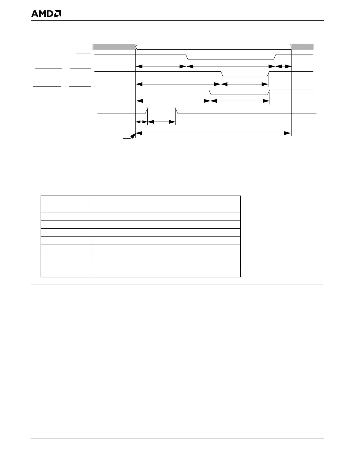
Figure 13-4 GP Bus Timing Format
13.5.1.2 Using GPRDY with Programmable Timing
If the GPRDY signal is used, the bus cycle can be extended as long as required by the
peripheral. GPRDY
cannot
be used to terminate any bus cycle earlier than programmed.
More detailed information is provided in “Wait States” on page 13-20.
13.5.1.3 Using GP Bus Echo Mode with Programmable Timing
While GP bus echo mode is enabled, the system designer needs to ensure that the GP
bus timing is not faster than that shown in Table 13-3. The minimum GP bus timing register
values during the GP bus echo mode are shown in Table 13-3.
GPA25
–
GPA0
GPCS
GPMEMRD or GPIORD
GPMEMWR or GPIOWR
GPALE
GPCSOFF + 1
GPRDOFF + 1
GPWROFF + 1
GPCSPW + 1
GPRDW + 1
GPWRW + 1
GPALEW + 1
GPCSRT + 1
Bus cycle durationBeginning of a bus cycle
GPALEOFF + 1
Address Valid
Notes:
1. Timing parameter values are in units of one internal clock period.
2. Timing parameters in the diagram can be adjusted via the corresponding GP bus registers.
3. GPCSOFF + GPCSPW + GPCSRT must be greater than or equal to GPRDOFF + GPRDW,
GPWROFF + GPWRW, or GPALEOFF + GPALEW.
4. The abbreviations in the figure refer to these GP bus registers:
Mnemonic Register
GPCSRT GP Chip Select Recovery Time
GPCSPW GP Chip Select Pulse Width
GPCSOFF GP Chip Select Offset
GPRDW GP Read Pulse Width
GPRDOFF GP Read Offset
GPWRW GP Write Pulse Width
GPWROFF GP Write Offset
GPALEW GP ALE Pulse Width
GPALEOFF GP ALE Offset