PCI Bus Host Bridge
Élan™SC520 Microcontroller User’s Manual 9-3
GPIRQ0 pins on the GP bus. See Chapter 15, “Programmable Interrupt Controller”, for
further information on connecting interrupt requests to the ÉlanSC520 microcontroller.
Figure 9-4 on page 9-5 shows how the PERR
and SERR signals are connected to the
ÉlanSC520 microcontroller. PERR
is driven by the PCI bus device (including the host
bridge) that is receiving data (sampling the AD31–AD0 bus during data phases). SERR
is
driven by external PCI bus devices that detect a system error. External pullups must be
provided for PERR
and SERR.
The PCI bus input and output pins of the ÉlanSC520 microcontroller are PCI bus revision
2.2 compliant. See the PCI bus specification for information on physical loading and routing.
The following PCI signals require pullups: FRAME
, IRDY, TRDY, STOP, DEVSEL, PERR,
and SERR
. These pullups must be provided externally to the ÉlanSC520 microcontroller
(the ÉlanSC520 microcontroller PCI bus pins do not have any termination).
The system PCI bus reset (RST
) signal is sourced from the ÉlanSC520 microcontroller and
is asynchronous to the PCI bus clock. See “Initialization” on page 9-29 for more information
on reset.
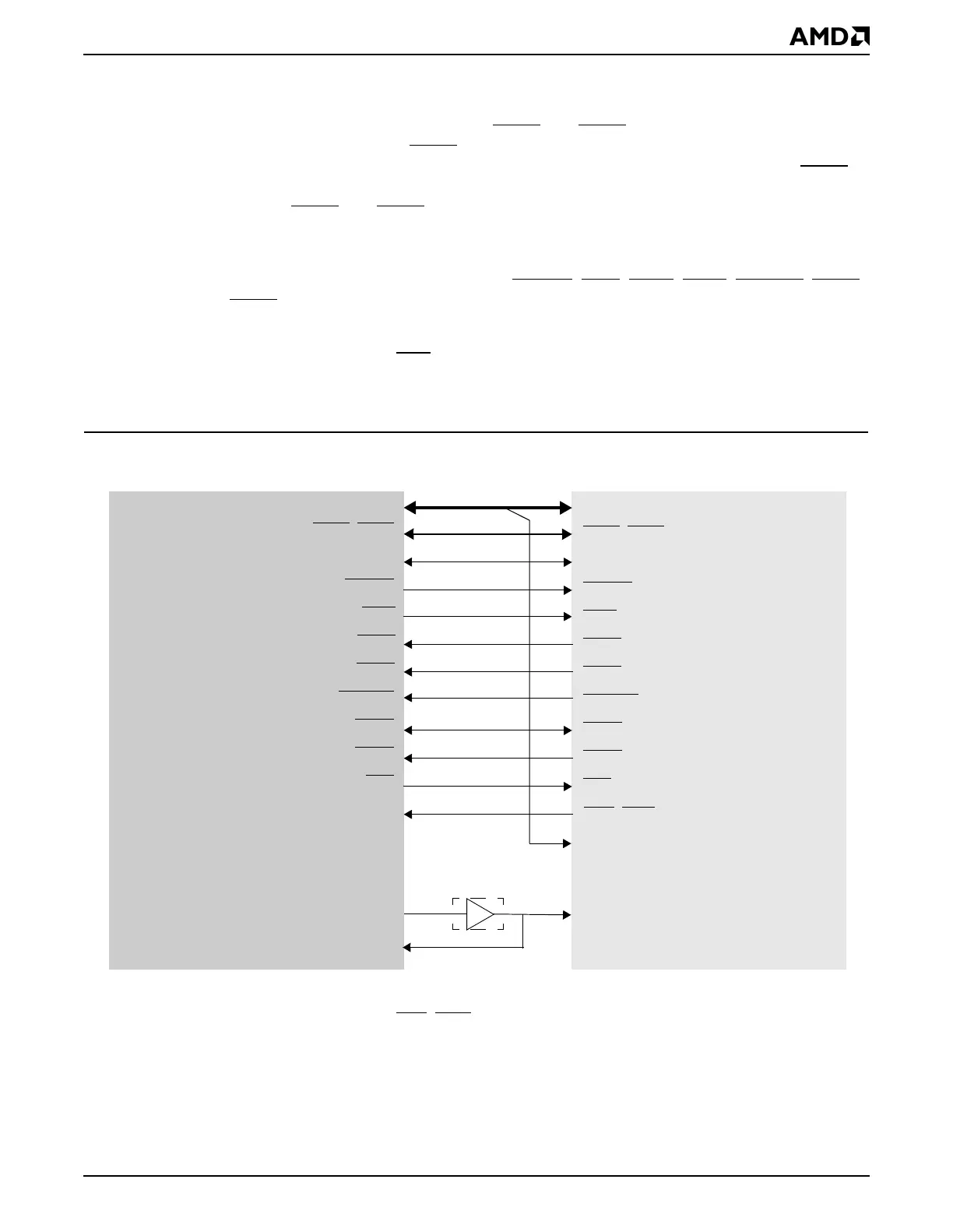
Figure 9-2 Élan™SC520 Microcontroller Connection to an External PCI Bus Target
PCI Target
Device
AD31–AD0
CBE3
–CBE0
PAR
FRAME
IRDY
TRDY
STOP
DEVSEL
PERR
SERR
RST
CLKPCIOUT
CLKPCIIN
AD31–AD0
CBE3–CBE0
PAR
FRAME
IRDY
TRDY
STOP
DEVSEL
PERR
SERR
RST
INTA–INTD
CLK
eODQ6&0LFURFRQWUROOHU
PCI Bus Host Bridge
(PCI bus master)
Notes:
1. INT implies any of the following pins: INTA
–INTD or GPIRQ10–GPIRQ0
INT
1
IDSEL
Clock Buffering
(optional)