General-Purpose Bus Controller
13-20 Élan™SC520 Microcontroller User’s Manual
The latest assertion time for these two signals is the same as the timing for the GPRDY
deassertion time (see “GPRDY Recognition” on page 13-20).
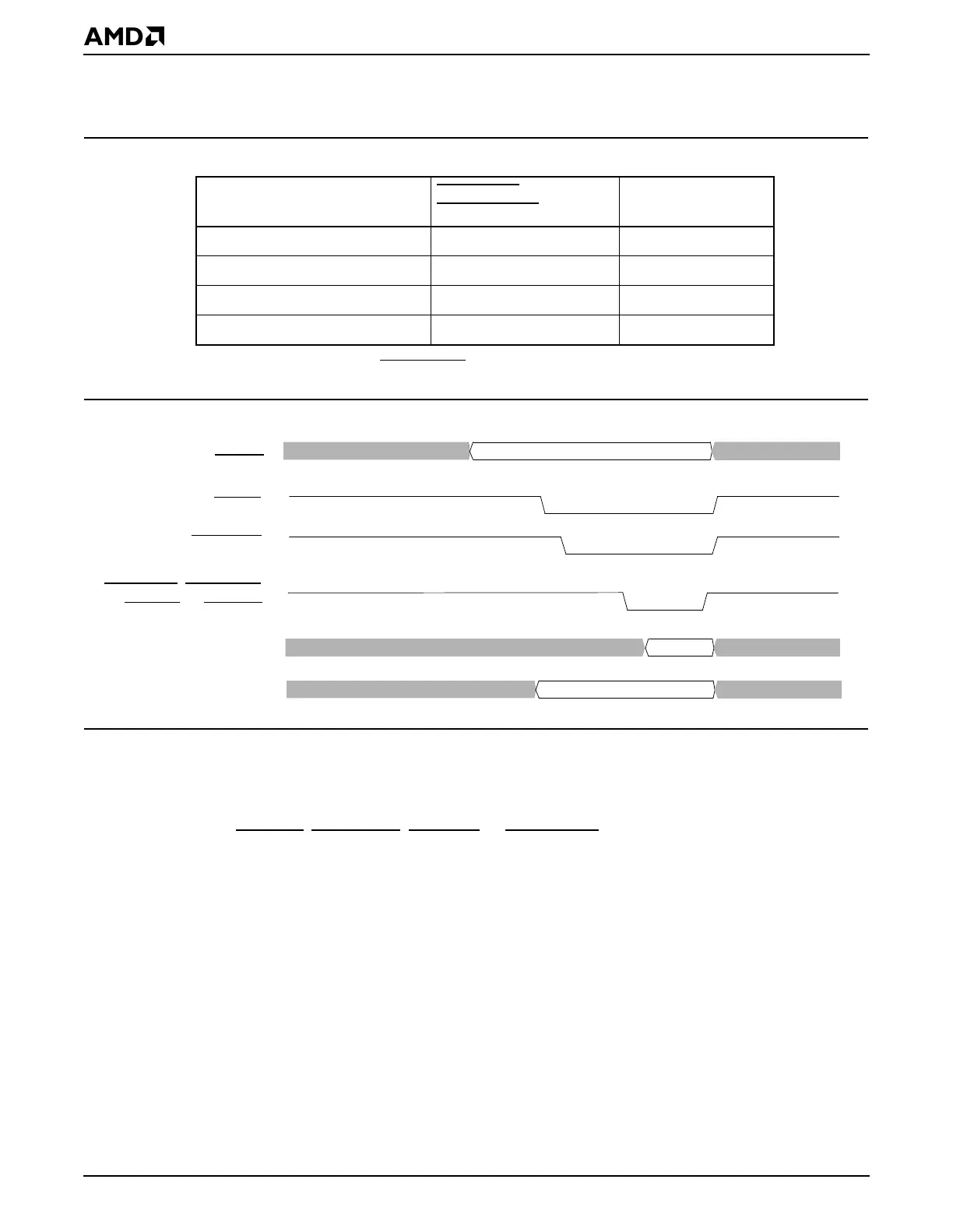
Figure 13-15 shows the GPIOCS16 timing for a 16-bit access and an 8-bit access.
Figure 13-15 16-Bit Access of a 16-Bit I/O Device
13.5.9.8 Wait States
The ÉlanSC520 microcontroller provides two ways to insert wait states in a GP bus cycle.
■ The user can program the programmable interface timing registers to delay the timing
of GPIORD
, GPMEMRD, GPIOWR, or GPMEMWR for the required number of wait state
cycles.
■ GPRDY can also be used to insert wait states dynamically on a cycle basis.
GPRDY can only be used to stretch GP bus cycles; it cannot be used to provide early
termination of the cycle. The control signals are always asserted for a minimum of the entire
period, as programmed in the timing control registers. Then, the additional delay can be
inserted by the deassertion of GPRDY.
Figure 13-16 shows the timing of GPRDY.
13.5.9.8.1 GPRDY Recognition
Assuming a 33.333-MHz crystal, the GPRDY pin must be deasserted a minimum of 45 ns
before the programmed deassertion of the command strobes and must have a minimum
deassertion (Low) width of 30 ns to insert a wait state into a GP bus cycle. Additional wait
states are inserted by extending the time in which the GPRDY pin is held deasserted. The
Table 13-8 Dynamic Bus Sizing Override of Programmed Data Width
GP Chip Select Data Width
(GPCSDW)
Register Setting
GPIOCS16
GPMEMCS16 Assertion Resultant Bus Size
8-bit Deasserted 8-bit
8-bit Asserted 16-bit
16-bit Deasserted 16-bit
16-bit Asserted 16-bit
Addr
Write Data
GPA23–GPA0,
GPCSx
GPIOCS16
GPD15–GPD0
Read Data
GPD15–GPD0
GPMEMRD
, GPMEMWR,
GPIORD, or GPIOWR
GPBHE