Synchronous Serial Interface
Élan™SC520 Microcontroller User’s Manual 22-7
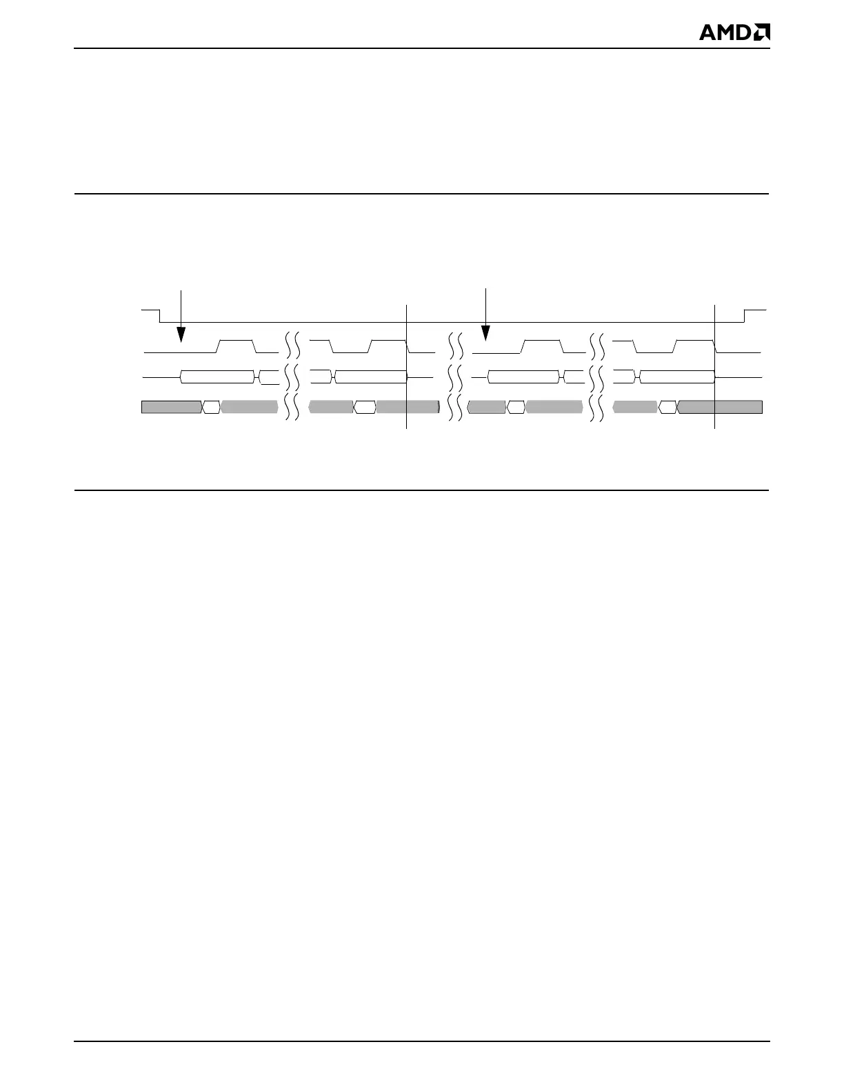
22.5.3.2 Burst, 16-Bit, and 32-Bit Cycles
Burst,16-bit, and 32-bit exchanges can be simulated by multiple 8-bit transactions. There
is at least one CPU clock period idle time between transactions. Additional delay between
each transaction is determined by software. Figure 22-8 shows an example of a 16-bit
operation. Two full-duplex SSI commands are executed to a Microwire-compatible
peripheral.
Figure 22-8 SSI Back-to-Back Transactions for Full-duplex,
Microwire-Compatible Configuration
22.5.4 Clocking Considerations
The SSI clock is derived from the 33-MHz clock. The CLK_SEL bit in the SSI Control
(SSICTL) register (MMCR offset CD0h) is used to configure the frequency of the SSI clock
(the SSI_CLK pin). The actual bit rate will vary, depending on whether the system is using
a 33.000-MHz or a 33.333-MHz crystal. See the
Élan™SC520 Microcontroller Register Set
Manual
, order #22005, for frequency selection.
22.5.5 Interrupts
An interrupt can be generated by the SSI to alert the CPU that a transaction is complete.
1. The interrupt is enabled by writing the TC_INT_ENB bit to a 1 in the SSI Control (SSICTL)
register.
2. When a transaction is complete, the BSY bit is cleared to a 0 in the SSI Status (SSISTA)
register (MMCR offset CD3h), the SSI Transaction Complete Interrupt (TC_INT) bit is
set to a 1 in the SSI Status (SSISTA) register, and an interrupt may be sent.
3. Hardware updates the SSI Status (SSISTA) register one-half an SSI clock period after
the last receive edge of a transaction (or one full SSI clock period after the last transmit
edge of a transaction, indicating that the SSI is again non-busy.
4. A 1 should be written back to the TC_INT bit to clear the bit and acknowledge the
interrupt; writing a 0 has no effect.
If the interrupt is not enabled, the SSI Status (SSISTA) register can be polled to periodically
read the BSY bit. BSY is set to a 1 when the SSI Command (SSICMD) register is loaded.
The TC_INT and BSY bit values for non-inverted and inverted phase modes are shown in
Figure 22-9.
7070
MSB LSB MSB LSB
PIOx
SSI_CLK
SSI_DO
SSI_DI
Transaction
complete
Transaction
complete
Command
Command