Execution Timing
PowerPC e500 Core Family Reference Manual, Rev. 1
Freescale Semiconductor 4-35
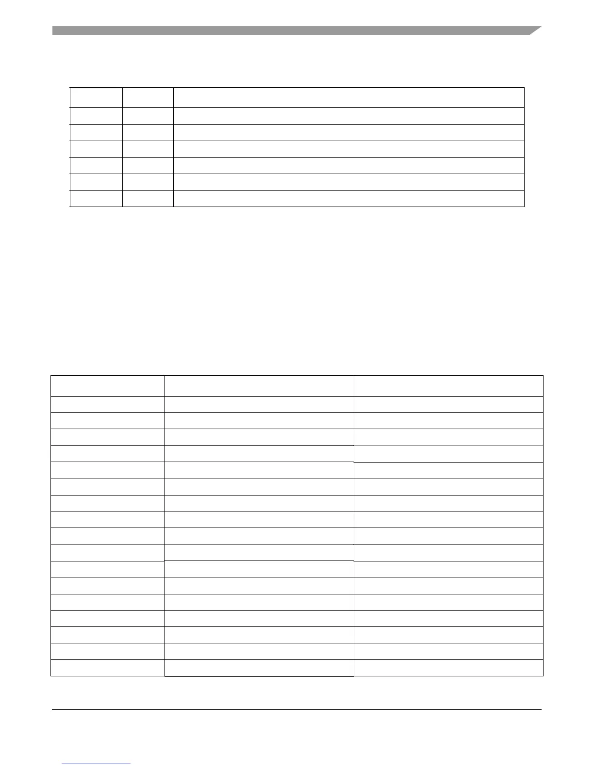
Table 4-7 shows load and store instruction latencies. Load/store multiple instruction cycles are
represented as a fixed number of cycles plus a variable number of cycles, where n represents the
number of words accessed by the instruction. Pipelined load/store instructions are shown with total
latency and throughput separated by a colon (latency:throughput).
subf[o][.]SU1 or SU21
1
tw SU1 or SU2 1
twi SU1 or SU2 1
xori SU1 or SU2 1
xoris SU1 or SU2 1
xor[.]SU1 or SU21
1
1
If the record bit is set, CR results are not available until after one more cycle. A subsequent instruction can execute
while CR results are generated.
2
The MU provides a bypass path that allows divide instructions to perform the iterative operations necessary for
division without blocking the MU pipeline (except to other divide instructions). Therefore, multiply instructions than
come after a divide instruction can finish execution ahead of the divide.
3
4:1 indicates 4-cycle latency. Once the pipeline is full, throughput is 1 instruction per clock cycle).
Table 4-7. LSU Instruction Latencies
Mnemonic Cycles (Latency:Throughput)
1
Serialization
2
dcba 3:1 Store
dcbf 3:1 Store
dcbi 3:1 —
dcblc 3:1 —
dcbst 3:1 Store
dcbt 3:1 —
dcbtls 3:1 —
dcbtst 3:1 —
dcbtstls 3:1 —
dcbz 3:1 Store
evldd 3:1 —
evlddx 3:1 —
evldh 3:1 —
evldhx 3:1 —
evldw 3:1 —
evldwx 3:1 —
evlhhesplat 3:1 —
Table 4-6. SU and MU PowerPC Instruction Execution Latencies (continued)
Mnemonic Unit Cycles