PowerPC e500 Core Family Reference Manual, Rev. 1
4-38 Freescale Semiconductor
Execution Timing
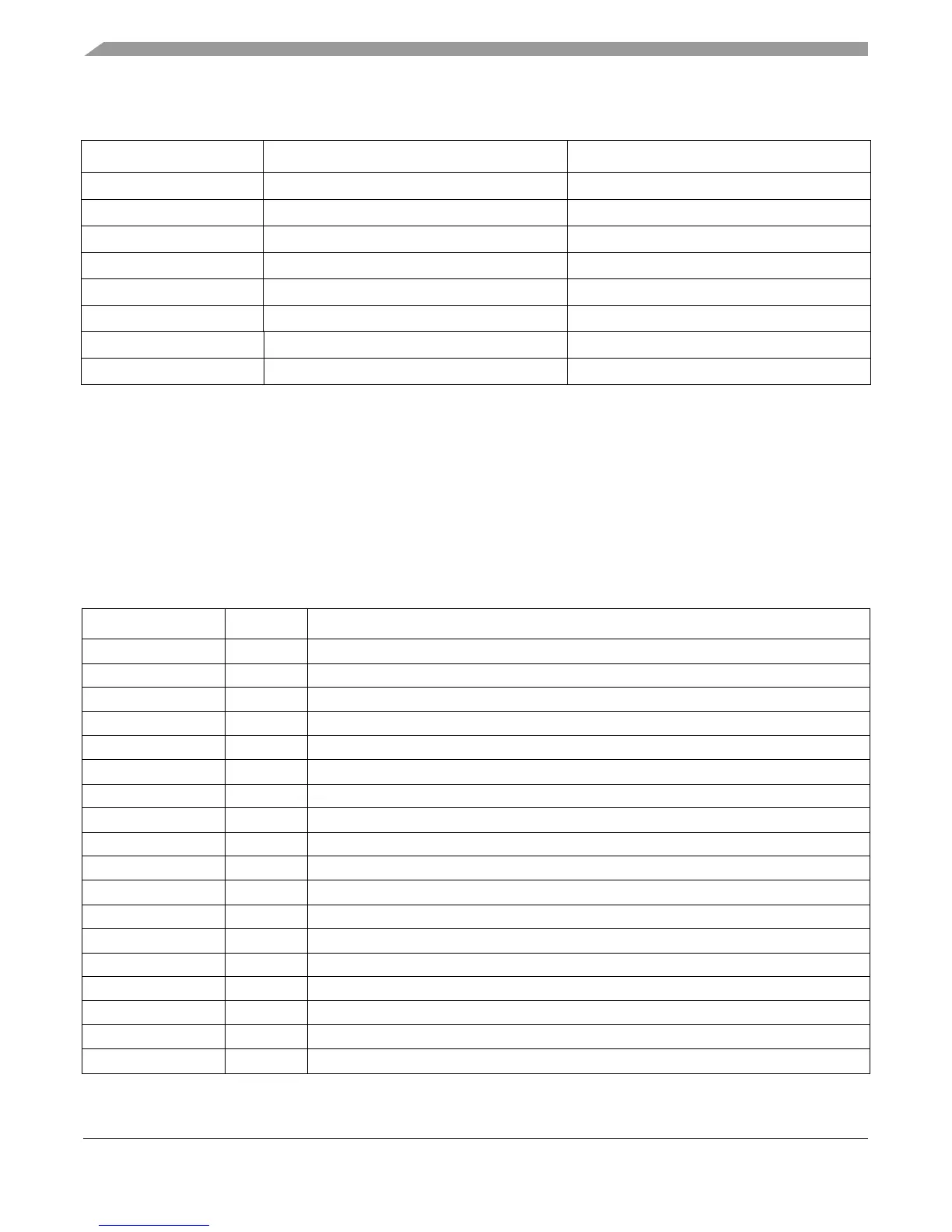
Table 4-8 lists instruction latencies for SPE and embedded floating-point computational and
logical instructions. SPE loads and stores are executed by the LSU and are described in Table 4-7.
stwcx. 3:1 Store, presync, postsync
stwu 3:1
3
Store
stwux 3:1
3
Store
stwx 3:1 Store
tlbivax 3:1 —
tlbre 3:1 Presync, postsync, move-to
tlbsx 3:1 Presync, postsync, move-to
tlbwe 3:1 Presync, postsync, move-to
1
For cache operations, the first number indicates the latency for finishing a single instruction; the second indicates the throughput
for a large number of back-to-back cache operations. The throughput cycle may be larger than the initial latency because more
cycles may be needed for the data to reach the cache. If the cache remains busy, subsequent cache operations cannot execute.
2
Section 4.3.3.3, “Instruction Serialization,” describes the different types of serializations listed here.
3
Load and store update instructions are broken into two instructions at dispatch, a load or store instruction that executes in the
LSU and an addi that executes in either SU. See Section 4.3.3.1, “GPR and CR Rename Register Operation.”
Table 4-8. SPE and Embedded Floating-Point APU Instruction Latencies
Mnemonic Unit Cycles (Latency:Throughput)
brinc SU1 or SU2 1
efdabs MU 6:1
efdadd MU 6:1
efdcfsf MU 6:1
efdcfsi MU 6:1
efdcfuf MU 6:1
efdcfui MU 6:1
efdcmpeq MU 6:1
efdcmpgt MU 6:1
efdcmplt MU 6:1
efdctsf MU 6:1
efdctsi MU 6:1
efdctsiz MU 6:1
efdctuf MU 6:1
efdctui MU 6:1
efdctuiz MU 6:1
efddiv MU
1
32
efdmul MU 6:1
Table 4-7. LSU Instruction Latencies (continued)
Mnemonic Cycles (Latency:Throughput)
1
Serialization
2