Appendix C Junction Board
C-5
5.BDE status display screen
2 SMS
6 ID
1 Version
2 Mainte No.
3 Class
4 ADE
5 BDE
6 MDM
7 Active SIM
8 Remote Mnt
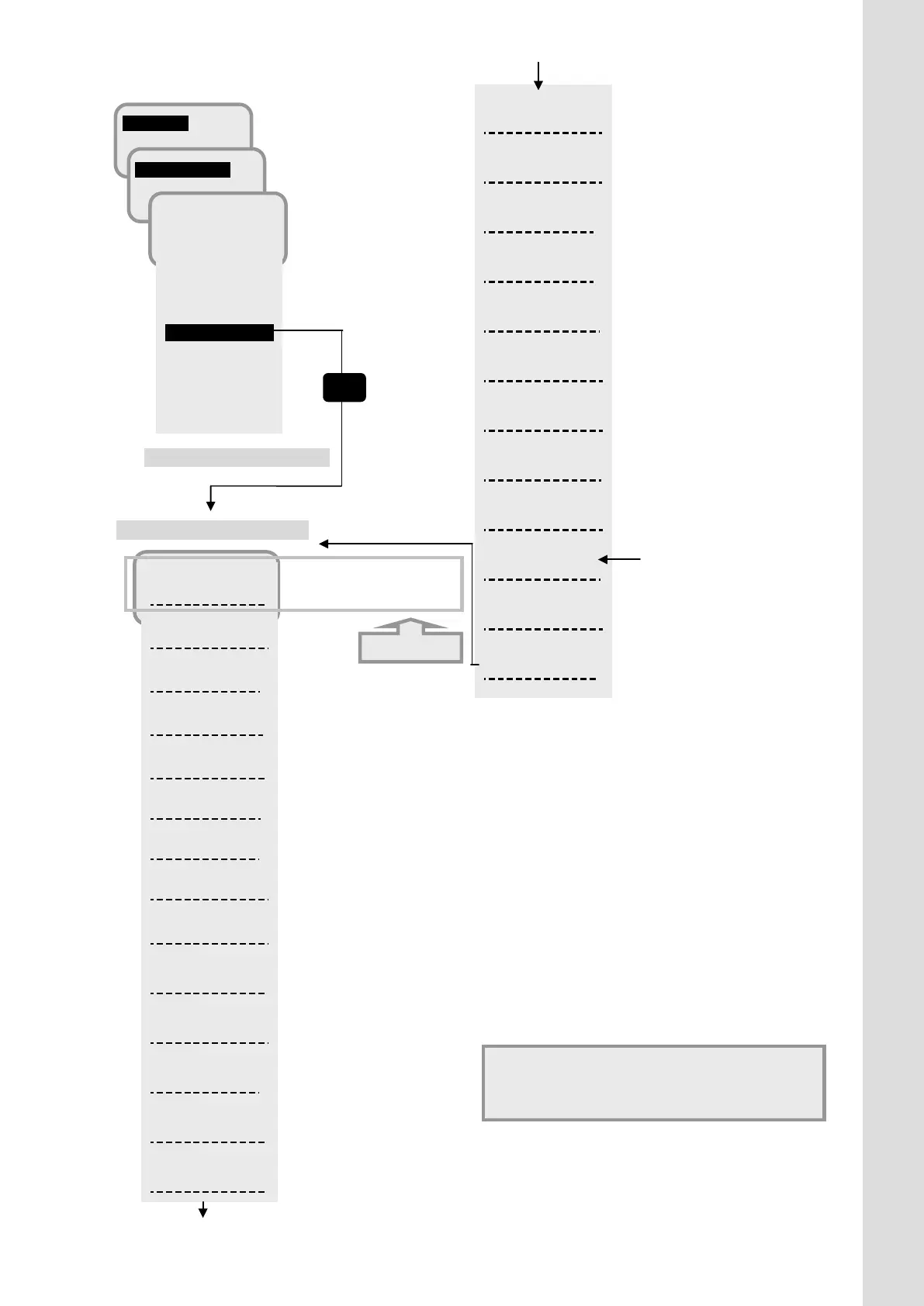
Fig.C.4b BDE status display screen
(when JB/GYRO are used)
NSK DIPSW:
0x00
BDE Status:
CS PS READY
Buzzer:
0000
Button:
0000
BPS Status:
0
ATT:
2
LAN:
000000
SIP Status:
Registered
IPTEL:
110100001
A:0000000000
00
23/MAR/2012
12:44:30
Tick:
0x000849AE5
….NSK unit Dip switch
…. BDE Status
….Buzzer Connection Status
( 0:Not connect, 1:Connect )
….Button Connection Status
( 0:Not connect, 1:Connect )
…. BPS Status
….BDE Attenuator (dB)
…. Ethernet port link Status
( 0:Not connect, 1:Connect )
…. SIP Registration Status *
(Registered/Not Registered/---)
…. IPTEL port link Status *
( 0:Not connect, 1:Connect )
…. Date
…..The timer since system boot
* Release software at end of
Heading:
0.0
Sat:
APAC
Spot Beam:
9
RNC ID
0x00
N 35.41 16
E 139.34 16
REC:
65
Ch Type
T1Q
Cable loss:
IMSI:
12378-901234-
Tracking:
NSK
GPS:
Int
GPS Status:
3D FIX
Calib Err:
0
Update Err:
0
(only when GYRO is used)
…Using satellite
….Spot Beam No.
….Stellite Satioin ID
….Position
….RECeiving level
….Received channel type
….ADE-BDE cable loss
….IMSI number stored in SIM card
…..Satellite tracking type
(Auto, Auto(Gyro), Sync/Step,
LAN, NMEA(4.8k), NMEA(38.4k))
….Using GPS
(Internal / External)
…. Position acquisition status
of GPS
…. Cable Calibration error
…. Software updating error
(Refer to p7-11) Normally displaying 0.
*About [Unit selection menu for Alarm Pack
(corresponded to Chapter 8.8.1),
the screen is changed in the same way.
Alarm bit display
Contents are not changed
from p7-10.
 Loading...


