3. Appearance
1 Power Switch
Turns power on and off.
2 SIM card slot
Mounts a SIM card.
3 LEDs
Indicates the communication/apparatus status. READY LED, ALARM LED and COMM LED lit in
the same way as LEDs on the Handset, except at the time of startup. Main unit has two more LEDs
(ANT. LED and SMS LED) on its front panel and indicates antenna status and new-SMS-receiving
status. The meanings and sequence of the LEDs are described in [Appendix P Front Panel LED lamps].
4 Handset port (12-PIN Modular Cable)
Connects with Handset unit.
Offered service: 4kbps Voice and SMS
5 TEL 1/2 ports (RJ-11 type 6-PIN Modular Cable)
Connects the analog equipment, terminal telephones, and facsimile to the main unit.
Offered services: 4kbps Voice and 64kbps 3.1kHz Audio
6 Antenna cable connector
Connects with the coaxial cable from the antenna (ADE).
7 ISDN port (RJ-45 type 8-PIN Modular Cable for ISDN)
Connects with equipment, which has an ISDN interface.
Offered services: 4kbps Voice, 64kbps 3.1kHz Audio, UDI, and RDI
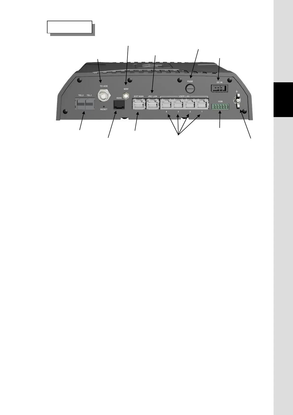
Rear view
Fig. 3.2c Main unit rear view
10. JRC LAN port
connector
9. Ext WAN port
 Loading...


