Insert Effects (IFX1…IFX12) Routing
741
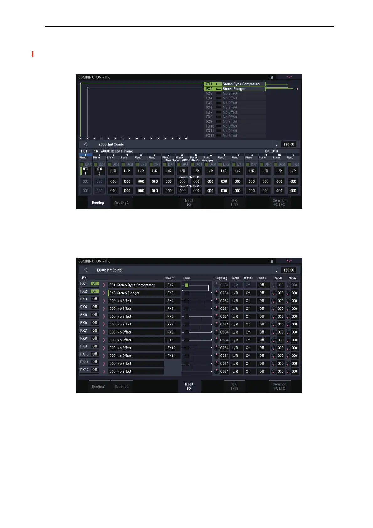
The following diagram (Fig. 2–2a) shows an example of
COMBINATION mode. The Timbre 1 output is sent to IFX1
and the Timbre 2 output is sent to IFX2 according to the Bus
Select setting. Other timbres are sent to L/R. The output
signal passes through the TFX1 and 2, then goes to AUDIO
OUTPUT (MAIN) L/MONO and R.
In the diagram (Fig. 2–2b), IFX1’s Chain check box is
checked and Chain to set to IFX2, sending the output of
IFX1 to IFX2. Timbre 1 is being processed by IFX1: 001:
Stereo Dyna Compressor and IFX2: 048: Stereo Flanger
effects. Timbre 2 is being processed by the IFX2: 048:
Stereo Flanger effect. The Routing Map area of the diagram
(Fig. 2–1a) shows these settings. (With these settings, IFX3–
12 are not being used.)

 Loading...