GUI Reference
R&S
®
ZNB/ZNBT
325User Manual 1173.9163.02 ─ 55
n
i
y
n
RMS
2
||
1
i 1
Note: To calculate the "Min", "Max", "Pk-Pk" and the "Std Dev" values, the analyzer
uses formatted response values y
i
(see trace formats). Consequently, the mean value
and the standard deviation of a trace depend on the selected trace format. In contrast,
the "RMS" calculation is based on linear, unformatted values. The physical unit for
unformatted wave quantities is 1 Volt. The RMS value has zero phase. The selected
trace format is applied to the unformatted RMS value, which means that the RMS
result of a trace does depend on the trace format.
Remote command:
CALCulate<Chn>:STATistics:MMPTpeak[:STATe]
CALCulate<Chn>:STATistics:MSTDdev[:STATe]
CALCulate<Chn>:STATistics:RMS[:STATe]
CALCulate<Chn>:STATistics:RESult?
CALCulate<Chn>:STATistics[:STATe]
CALCulate<Chn>:STATistics[:STATe]:AREA
Format
This setting determines how Min/Max/Peak-Peak, Mean/Std Dev/RMS for complex-val-
ued traces (Smith, Polar) are calculated:
●
"ZVAB": the results are based on unformatted wave quantities (voltages)
●
"R + jX": the results are based on the impedance values R and X
●
"G + jB": the results are based on the admittance values G and B
In the two latter cases, the "RMS" value is not displayed.
Remote command:
CALCulate<Chn>:STATistics:FORMat
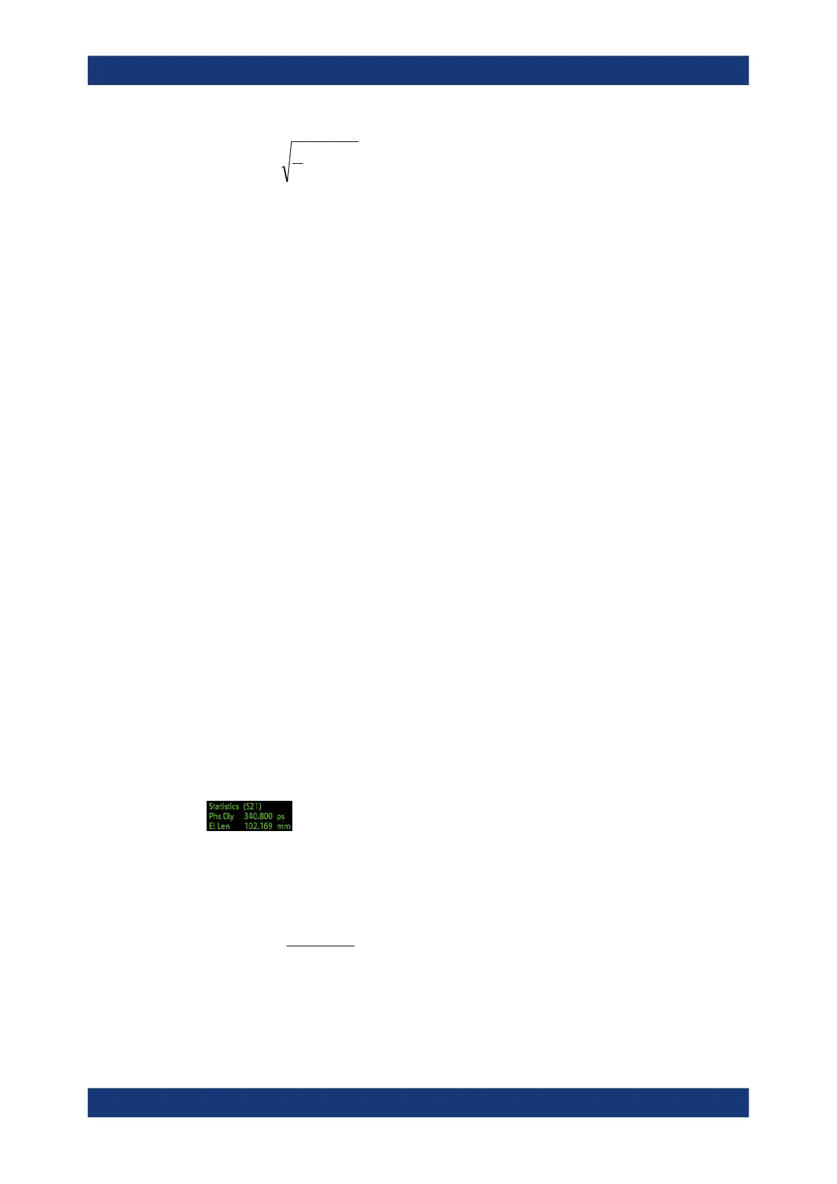
Phase/El Length
Displays or hides the phase delay ("Phs Dly") and the electrical length ("El Len") of the
trace in the selected evaluation range ("Evaluation Range..."). The parameters are only
available for trace formats that contain phase information, i.e. for the formats "Phase",
"Unwr Phase", and the polar diagram formats "Polar", "Smith", "Inv Smith" (see Chap-
ter 6.3, "Format Softtool", on page 288). Moreover, the sweep type must be a fre-
quency sweep, and the evaluation range must contain at least 3 measurement points.
The phase parameters are obtained from an approximation to the derivative of the
phase in the selected evaluation range.
●
"Phs Dly" is the phase delay, which is an approximation to the group delay and cal-
culated as follows:
f
PD
deg
360
where Δf is the width of the evaluation range and ΔΦ is the corresponding phase
change. See also note on transmission and reflection parameters below.
Trace Config Softtool

 Loading...


