GUI Reference
R&S
®
ZNB/ZNBT
541User Manual 1173.9163.02 ─ 55
The "Driving Mode" setting is also used during a system error correction. For channels
which require a single partial measurement only, the driving mode settings are equiva-
lent. See also Chapter 5.1.4.1, "Partial Measurements and Driving Mode", on page 83.
Remote command:
[SENSe<Ch>:]COUPle
Image Suppr.
The "Image Suppr." settings define whether the analyzer measures with a local oscilla-
tor frequency LO below or above the RF input frequency. This feature can be used to
eliminate known spurious components in the input signal that can distort the measure-
ment, especially in the low frequency range.
●
In "Auto" mode, the analyzer auto-selects the LO frequency, depending on the
receiver (RF) frequency and the test port. This mode systematically avoids known
spurious signals if no frequency conversion occurs in the test setup.
●
"LO < RF" means that the LO frequency is always below the measured RF fre-
quency. This mode is appropriate for avoiding single, known spurious signals.
●
"LO > RF" means that the LO frequency is always above the measured RF fre-
quency. This mode is appropriate for avoiding single, known spurious signals.
Tip: In the presence of several spurious signals, setting the "Image Suppr." parameter
globally can be insufficient. To improve the result, perform a segmented frequency
sweep and assign independent LO frequencies to the individual sweep segments.
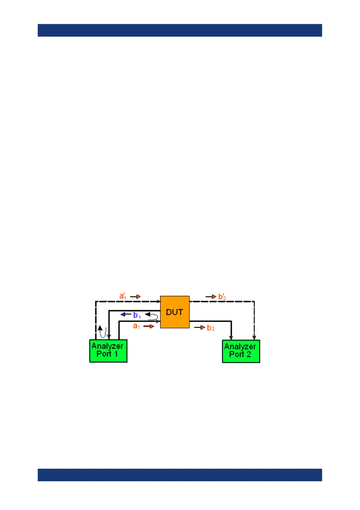
Application example
Consider the following test setup with a strongly reflecting DUT (e.g. a bandpass in its
stop band) that is measured in transmission. The incident wave a
1
is generated at a
frequency RF. The reflected wave b
1
falls into the receiver mixer of the analyzer port 1;
a small fraction of the mixer product RF + 2*IF can be reflected back towards the DUT.
If this spurious wave a'
1
passes the DUT, then it is received as b'
2
at port 2, together
with the wanted signal b
2
.
LO > RF implies that LO = RF + IF. The mixer at port 2 converts both the wanted signal
b
2
and the spurious signal b'
2
which is at the frequency RF' = IF + LO, to the same IF
frequency. The response of an ideal, infinitely steep bandpass filter with a pass band
between B
-
and B
+
looks as follows:
Channel Config Softtool

 Loading...


