GUI Reference
R&S
®
ZNB/ZNBT
602User Manual 1173.9163.02 ─ 55
If the "Fixture Simulator" is disabled for the related channel (see "Fixture Simulator"
on page 512), this tab is inactive, i.e. all controls except the "Overview" button are
grayed out.
Overview
See "Overview" on page 579.
Type
Switches between "Deembedding" and "Embedding" network definition.
Port Set
Port sets, defined in the complementary Port Sets Panel dock widget panel. The trans-
formation networks are defined such that the physical analyzer test ports are connec-
ted to the left of the circuit; the DUT ports are on the right side. You can define inde-
pendent transformation networks for all port sets.
The port set number, i.e. the number at the beginning of each "Port Set" item, corre-
sponds to the position of the port set in the Port Sets Panel.
Remote command:
The port set number corresponds to the <ListId> numeric suffix in the port set de-/
embedding commands; see e.g. CALCulate<Ch>:TRANsform:VNETworks:PPAir:
DEEMbedding<ListId>[:STATe].
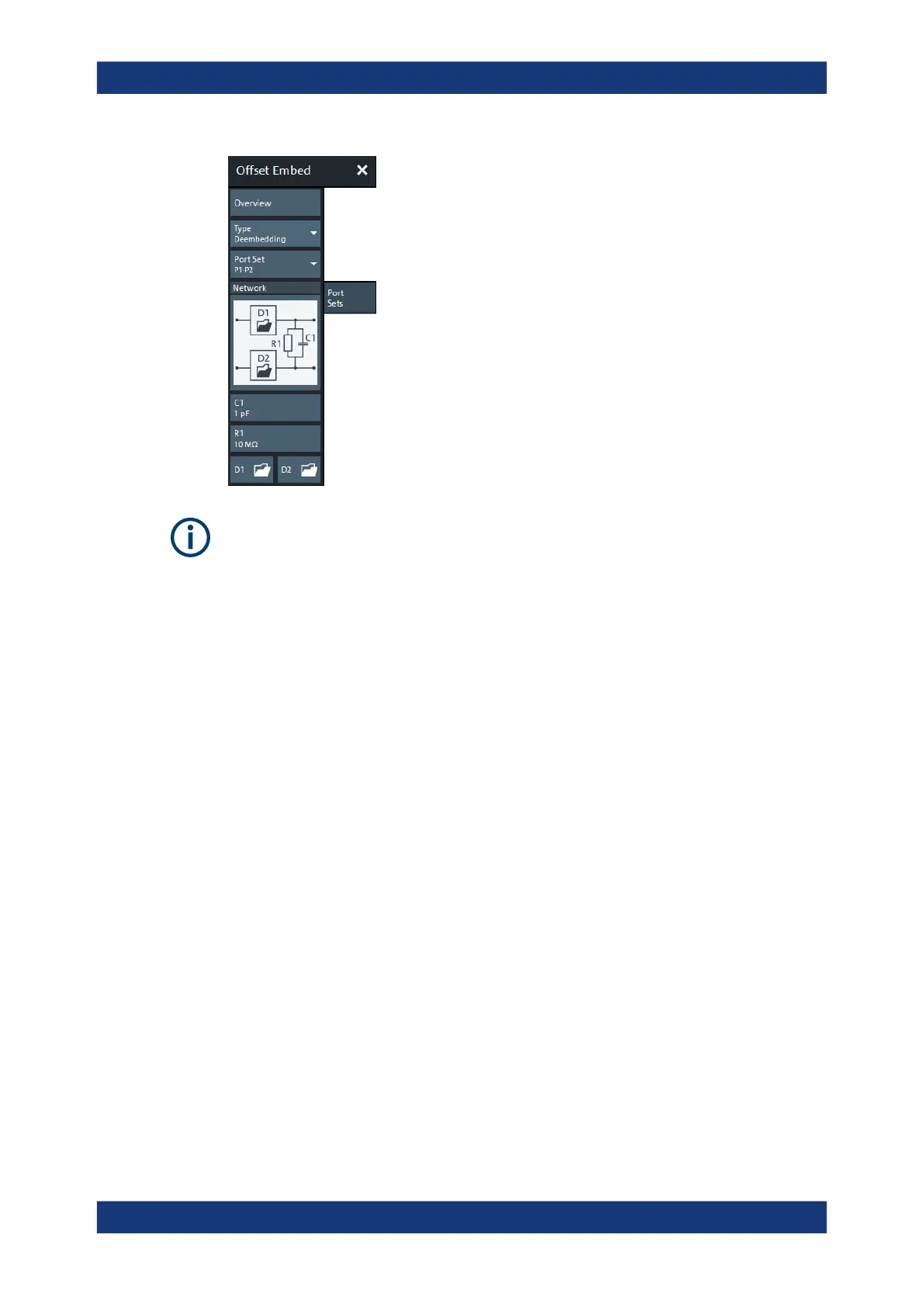
Network
Depending on the size m of the selected port set, the graphical list contains all availa-
ble 2m-port deembedding/embedding networks.
Note: For port pairs (m=2) the deembedding/embedding network can be defined either
via lumped element models (in combination with s2p Touchstone files) or via a s4p
Touchstone file (see Chapter 5.6.2.5, "Port Pair De-/Embedding", on page 193). For
m≥3, there are no predefined lumped element models available; the deembedding/
embedding network has to be defined via an s<2m>p Touchstone file.
Offset Embed Softtool

 Loading...


