GUI Reference
R&S
®
ZNB/ZNBT
605User Manual 1173.9163.02 ─ 55
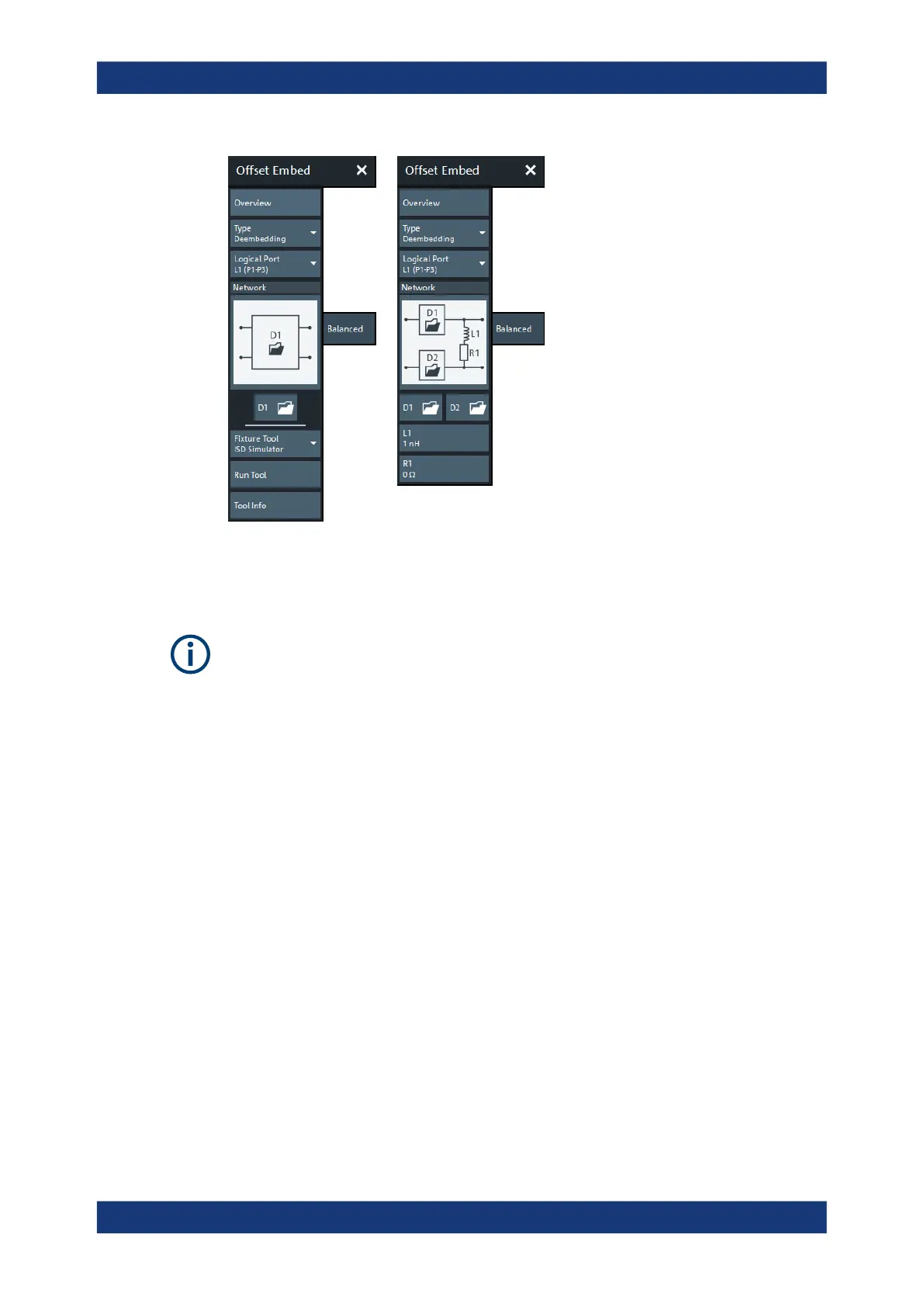
Figure 6-58: Offset Embed > Balanced softtool
left = 4 port data file selected for de-/embedding
right = other network selected for de-/embedding
If the "Fixture Simulator" is disabled for the related channel (see "Fixture Simulator"
on page 512), this tab is inactive, i.e. all controls except the "Overview" button are
grayed out.
Overview
See "Overview" on page 579.
Type
Switches between "Deembedding" and "Embedding" network definition.
Logical Port
Logical analyzer port, as defined in the "Balanced Ports" configuration. The transfor-
mation networks are defined such that the physical analyzer test ports are connected
to the left of the circuit; the DUT ports are on the right side.
You can define independent transformation networks for all balanced ports.
Remote command:
The <LogPt> numeric suffix in the embedding/deembedding commands identifies the
logical port; see e.g. CALCulate<Ch>:TRANsform:VNETworks:BALanced:
EMBedding<LogPt>[:STATe].
Network
The graphical list contains all available 4-port networks (see Chapter 5.6.2.4, "Circuit
Models for 4-Port Networks", on page 191).
Offset Embed Softtool

 Loading...


