COPY IMAGE ADJUSTMENT: PRINTING/SCANNING
SM 3-189 B234/B235/B236/D101/D102/D103
Replacement
Adjustment
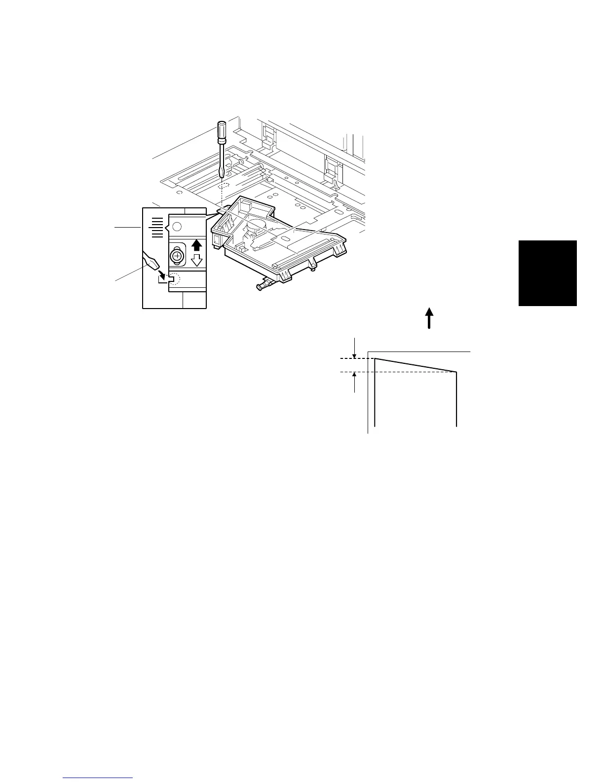
6. Make a note of the position of the laser unit using the scale [A].
7. Adjust the laser unit position using a flat screwdriver [B] as shown.
If the right side of the trimming area pattern is down by about 1 mm as shown
[C], the laser unit should be rotated about one graduation in the direction of the
black arrow. If the opposite side is down, adjust in the opposite direction.
8. Tighten the three screws to secure the laser unit.
9. Print the trimming area pattern to check the image. If it is still the same, repeat
steps 2 to 7.
B234R886.WMF
1 mm
Feed Direction
B234R885.WMF
[A]
[C]
[B]
 Loading...


