Board Structure
B234/B235/B236/D101/D102/D103 6-42 SM
Board LEDs
Normal Operation
With the exception of the controller board, relay board, and the PCBs of the three
CIS image position sensors, the LEDs of the other boards light GREEN while they
are operating (supplied with power).
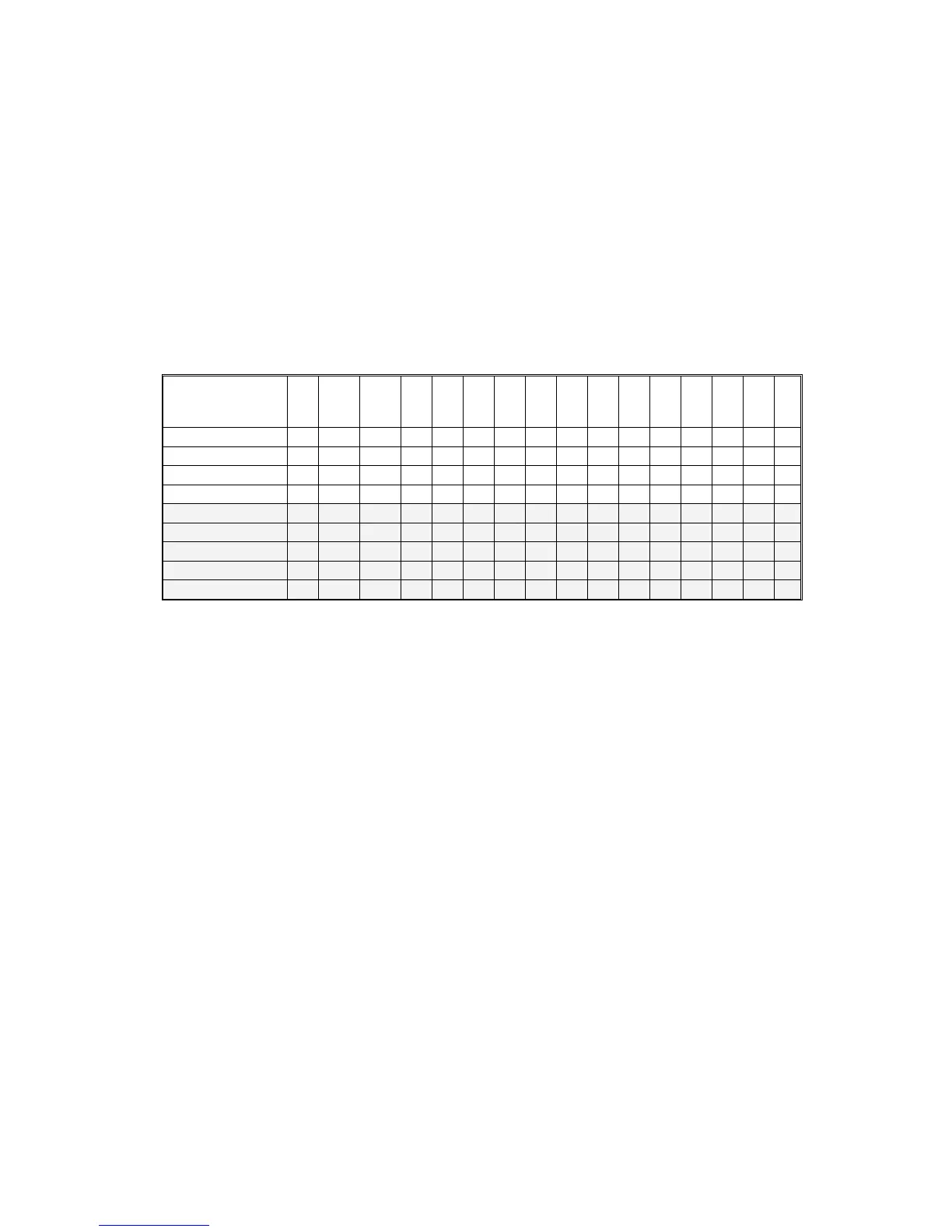
In the low power mode, the PSU shuts down boards that are not essential for
running the machine in lower power mode, to conserve energy.
The shaded areas of the table below show the circuits that are shut down by the
PSU in the low power mode.
CTL
MB
HDD
IPU
BCU
IOB
AC
PP
MCU
LDB
OPU
SIB
SBU
ADF
FIN
LCT
5VE
O O O O
12VE
O O
5VL
O O O O
O
5VLINT
O O
O
5V
O
O
O
24V
O
O O O O O O O O
24VINT
O
O
24VCNT
O
38V
O
O
In the low power mode, power is supplied to parts of the controller, BCU, IOB, AC
boards, and the operation panel, so that the controller, operation panel and fusing
temperature control can continue to operate. All other operations of the mainframe
and finishers are shut down.
Recovery From Low Power Mode
Only two actions awaken the machine from low power mode: 1) pressing a key on
the operation panel, and 2) setting an original on the ADF.