RM0008 Connectivity line devices: reset and clock control (RCC)
Doc ID 13902 Rev 12 125/1096
External source (HSE bypass)
In this mode, an external clock source must be provided. It can have a frequency of up to
50 MHz. You select this mode by setting the HSEBYP and HSEON
bits in the Clock control
register (RCC_CR). The external clock signal (square, sinus or triangle) with ~50% duty
cycle has to drive the OSC_IN pin while the OSC_OUT pin should be left hi-Z. See
Figure 12.
External crystal/ceramic resonator (HSE crystal)
The 3 to 25 MHz external oscillator has the advantage of producing a very accurate rate on
the main clock.
The associated hardware configuration is shown in Figure 12. Refer to the electrical
characteristics section of the datasheet for more details.
The HSERDY flag in the Clock control register (RCC_CR) indicates if the high-speed
external oscillator is stable or not. At startup, the clock is not released until this bit is set by
hardware. An interrupt can be generated if enabled in the Clock interrupt register
(RCC_CIR).
The HSE crystal can be switched on and off using the HSEON bit in the Clock control
register (RCC_CR).
8.2.2 HSI clock
The HSI clock signal is generated from an internal 8 MHz RC Oscillator and can be used
directly as a system clock or divided by 2 to be used as PLL input.
The HSI RC oscillator has the advantage of providing a clock source at low cost (no external
components). It also has a faster startup time than the HSE crystal oscillator however, even
with calibration the frequency is less accurate than an external crystal oscillator or ceramic
resonator.
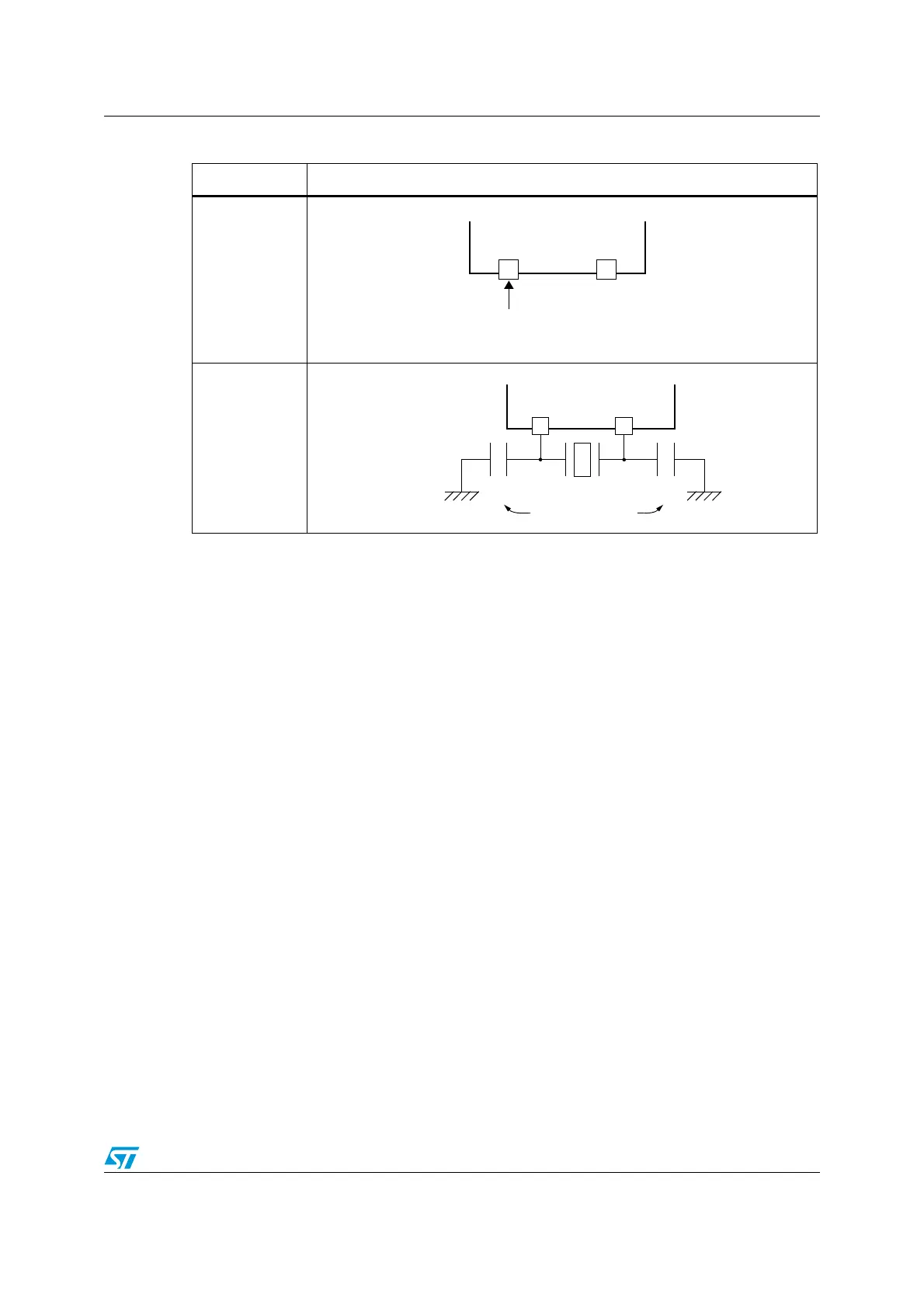
Figure 12. HSE/ LSE clock sources
Clock source Hardware configuration
External clock
Crystal/ceramic
resonators
OSC_OUT
External
source
(HiZ)
OSC_IN OSC_OUT
Load
capacitors
C
L2
C
L1
 Loading...


