RM0008 DMA controller (DMA)
Doc ID 13902 Rev 12 273/1096
13.4 DMA registers
Refer to Section 2.1 on page 46 for a list of abbreviations used in register descriptions.
Note: In the following registers, all bits related to channel6 and channel7 are not relevant for DMA2
since it has only 5 channels.
The peripheral registers can be accessed by bytes (8-bit), half-words (16-bit) or words (32-
bit).
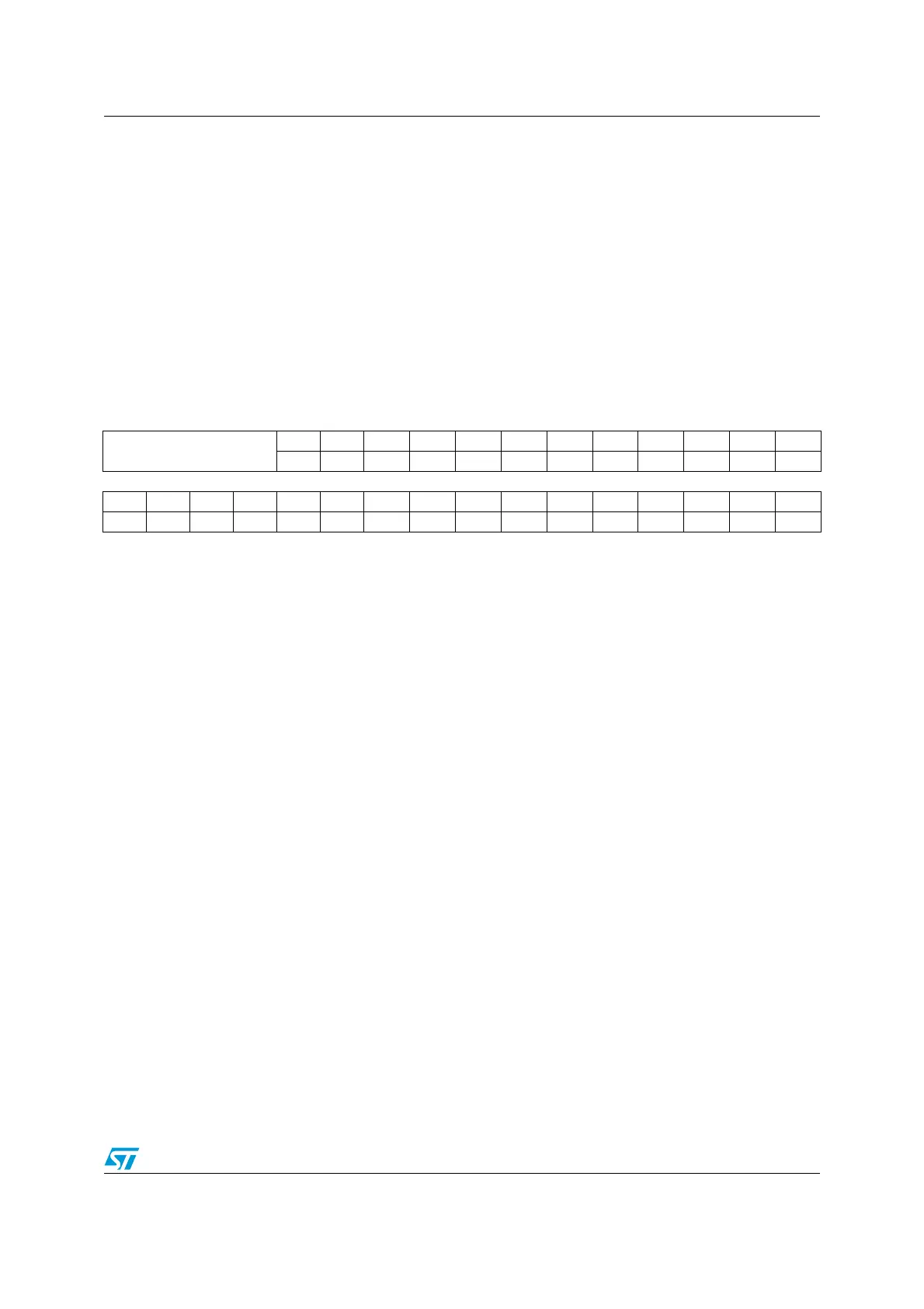
13.4.1 DMA interrupt status register (DMA_ISR)
Address offset: 0x00
Reset value: 0x0000 0000
31 30 29 28 27 26 25 24 23 22 21 20 19 18 17 16
Reserved
TEIF7 HTIF7 TCIF7 GIF7 TEIF6 HTIF6 TCIF6 GIF6 TEIF5 HTIF5 TCIF5 GIF5
rrrrrrrrrrrr
1514131211109876543210
TEIF4 HTIF4 TCIF4 GIF4 TEIF3 HTIF3 TCIF3 GIF3 TEIF2 HTIF2 TCIF2 GIF2 TEIF1 HTIF1 TCIF1 GIF1
rrrrrrr r r r rrrrrr
Bits 31:28 Reserved, always read as 0.
Bits 27, 23, 19, 15,
11, 7, 3
TEIFx: Channel x transfer error flag (x = 1 ..7)
This bit is set by hardware. It is cleared by software writing 1 to the corresponding bit in the
DMA_IFCR register.
0: No transfer error (TE) on channel x
1: A transfer error (TE) occurred on channel x
Bits 26, 22, 18, 14,
10, 6, 2
HTIFx: Channel x half transfer flag (x = 1 ..7)
This bit is set by hardware. It is cleared by software writing 1 to the corresponding bit in the
DMA_IFCR register.
0: No half transfer (HT) event on channel x
1: A half transfer (HT) event occurred on channel x
Bits 25, 21, 17, 13,
9, 5, 1
TCIFx: Channel x transfer complete flag (x = 1 ..7)
This bit is set by hardware. It is cleared by software writing 1 to the corresponding bit in the
DMA_IFCR register.
0: No transfer complete (TC) event on channel x
1: A transfer complete (TC) event occurred on channel x
Bits 24, 20, 16, 12,
8, 4, 0
GIFx: Channel x global interrupt flag (x = 1 ..7)
This bit is set by hardware. It is cleared by software writing 1 to the corresponding bit in the
DMA_IFCR register.
0: No TE, HT or TC event on channel x
1: A TE, HT or TC event occurred on channel x
 Loading...


