RM0008 Controller area network (bxCAN)
Doc ID 13902 Rev 12 633/1096
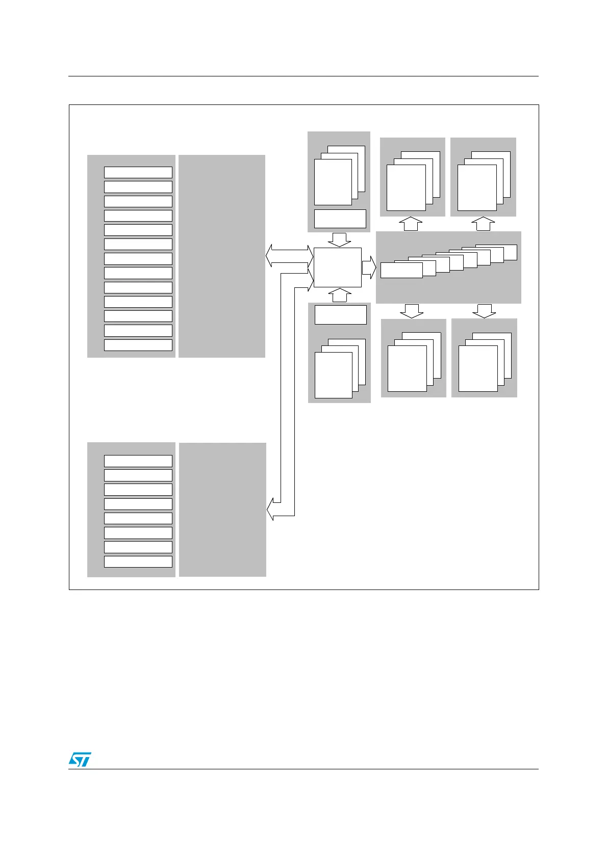
Figure 222. Dual CAN block diagram (connectivity devices)
24.4 bxCAN operating modes
bxCAN has three main operating modes: initialization, normal and Sleep. After a
hardware reset, bxCAN is in Sleep mode to reduce power consumption and an internal pull-
up is active on CANTX. The software requests bxCAN to enter initialization or Sleep mode
by setting the INRQ or SLEEP bits in the CAN_MCR register. Once the mode has been
entered, bxCAN confirms it by setting the INAK or SLAK bits in the CAN_MSR register and
the internal pull-up is disabled. When neither INAK nor SLAK are set, bxCAN is in normal
mode. Before entering normal mode bxCAN always has to synchronize on the CAN bus.
26
..
Acceptance Filters
..
3
2
1
Filter
0
27
Transmission
Scheduler
Mailbox 0
1
2
Receive FIFO 1
Mailbox 0
1
2
Receive FIFO 0
Mailbox 0
1
2
Tx Mailboxes
Transmission
Scheduler
Mailbox 0
1
2
Receive FIFO 1
Mailbox 0
1
2
Receive FIFO 0
Mailbox 0
1
2
Tx Mailboxes
Memory
Access
Controller
Master Control
Master Status
Rx FIFO 0 Status
Rx FIFO 1 Status
Error Status
Bit Timing
Interrupt Enable
Control/Status/Configuration
Tx Status
Master Control
Master Status
Rx FIFO 0 Status
Rx FIFO 1 Status
Error Status
Bit Timing
Filter Mode
Filter Scale
Interrupt Enable
Control/Status/Configuration
Tx Status
Filter FIFO Assign
Filter Master
Filter Activation
CAN 2.0B Active Core
CAN2 (Slave)
CAN 2.0B Active Core
CAN1 (Master) with 512 bytes SRAM
Master
retsaMretsaM
Master Filters
Slave
Slave
Slave
Slave Filters
(n to 27)
(0 to n)
Note: CAN 2 start filter bank number n is configurable by writing to
the CAN2SB[5:0] bits in the CAN_ FMR register.
ai16094
 Loading...


