Serial peripheral interface (SPI) RM0008
694/1096 Doc ID 13902 Rev 12
25.3.9 SPI communication using DMA (direct memory addressing)
To operate at its maximum speed, the SPI needs to be fed with the data for transmission and
the data received on the Rx buffer should be read to avoid overrun. To facilitate the transfers,
the SPI features a DMA capability implementing a simple request/acknowledge protocol.
A DMA access is requested when the enable bit in the SPI_CR2 register is enabled.
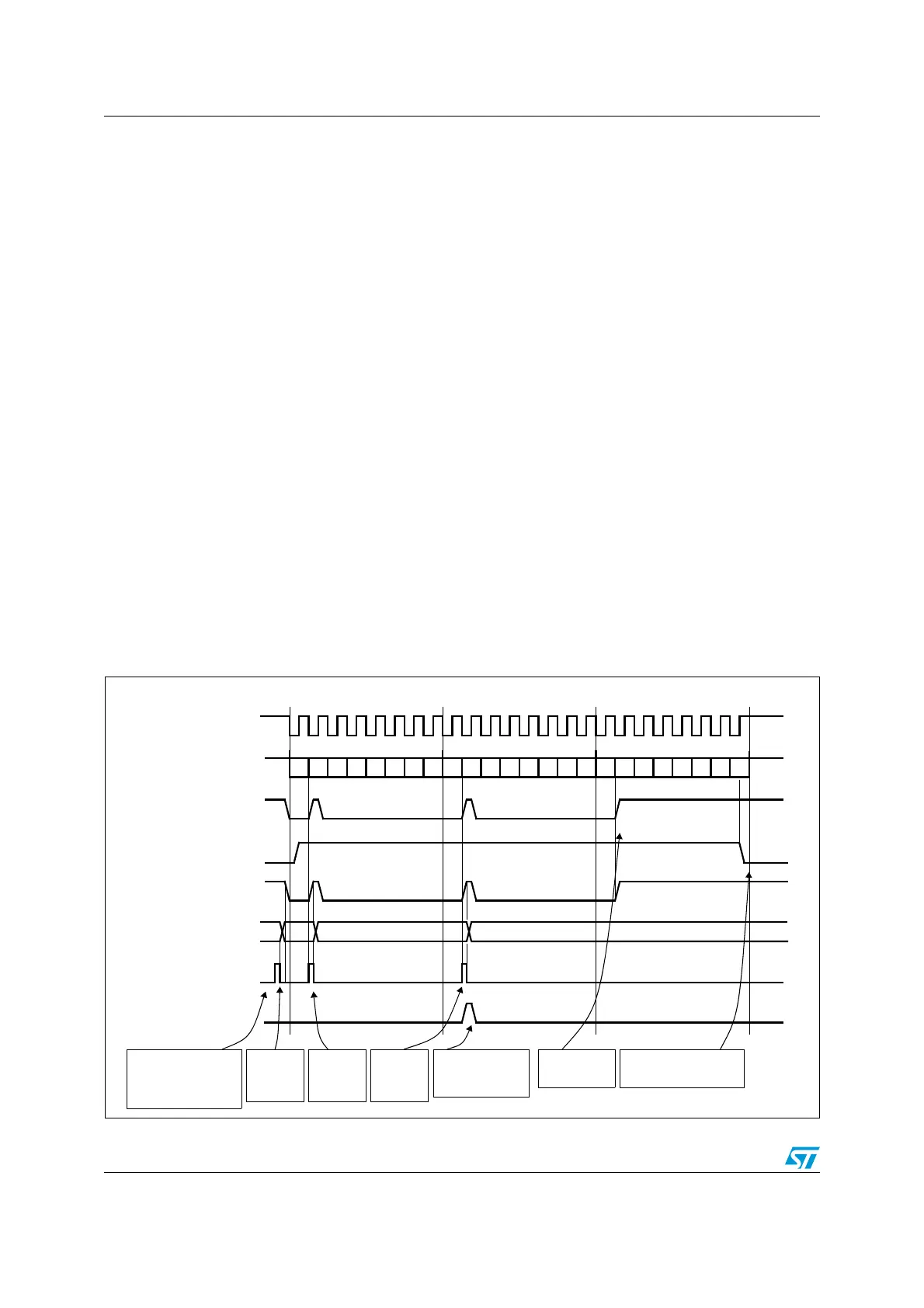
Separate requests must be issued to the Tx and Rx buffers (see Figure 246 and
Figure 247):
● In transmission, a DMA request is issued each time TXE is set to 1. The DMA then
writes to the SPI_DR register (this clears the TXE flag).
● In reception, a DMA request is issued each time RXNE is set to 1. The DMA then reads
the SPI_DR register (this clears the RXNE flag).
When the SPI is used only to transmit data, it is possible to enable only the SPI Tx DMA
channel. In this case, the OVR flag is set because the data received are not read.
When the SPI is used only to receive data, it is possible to enable only the SPI Rx DMA
channel.
In transmission mode, when the DMA has written all the data to be transmitted (flag TCIF is
set in the DMA_ISR register), the BSY flag can be monitored to ensure that the SPI
communication is complete. This is required to avoid corrupting the last transmission before
disabling the SPI or entering the Stop mode. The software must first wait until TXE=1 and
then until BSY=0.
Note: During discontinuous communications, there is a 2 APB clock period delay between the
write operation to SPI_DR and the BSY bit setting. As a consequence, it is mandatory to
wait first until TXE=1 and then until BSY=0 after writing the last data.
Figure 246. Transmission using DMA
0xF1
Tx buffer
TXE flag
0xF2
BSY flag
0xF3
set by hardware
clear by DMA write
set by hardware
cleared by DMA write
set by hardware
set by hardware
SCK
reset
Example with CPOL=1, CPHA=1
(write to SPI_DR)
MISO/MOSI (out)
DATA 1 = 0xF1
DATA 2 = 0xF2
DATA 3 = 0xF3
software configures the
DMA SPI Tx channel
to send 3 data items
and enables the SPI
DMA writes to SPI_DR
DMA request
ignored by the DMA because
DMA TCIF flag
set by hardware clear by software
DMA writes
DATA1 into
SPI_DR
by hardware
DMA writes
DATA2 into
SPI_DR
DMA writes
DATA3 into
SPI_DR
software waits until BSY=0
(DMA transfer complete)
DMA transfer is
complete (TCIF=1 in
DMA_ISR)
software waits
until TXE=1
DMA transfer is complete
b0 b1 b2 b3 b4 b5 b 6 b7 b0 b1 b2 b3 b4 b5 b6 b7
b0 b1 b2 b3 b4 b5 b6 b7
ai17349

 Loading...


