USB on-the-go full-speed (OTG_FS) RM0008
936/1096 Doc ID 13902 Rev 12
6. In Negotiated mode, the OTG_FS controller detects the suspend, disconnects, and
switches back to the host role. The OTG_FS controller asserts the DM pull down and
DM pull down in the PHY to indicate its assumption of the host role.
7. The OTG_FS controller sets the Connector ID status change interrupt in the OTG
Interrupt Status register. The application must read the connector ID status in the OTG
Control and Status register to determine the OTG_FS controller operation as an A-
device. This indicates the completion of HNP to the application. The application must
read the Current mode bit in the OTG control and status register to determine host
mode operation.
8. The B-device connects, completing the HNP process.
B-device host negotiation protocol
HNP switches the USB host role from B-device to A-device. The application must set the
HNP-capable bit in the Core USB configuration register to enable the OTG_FS controller to
perform HNP as a B-device.
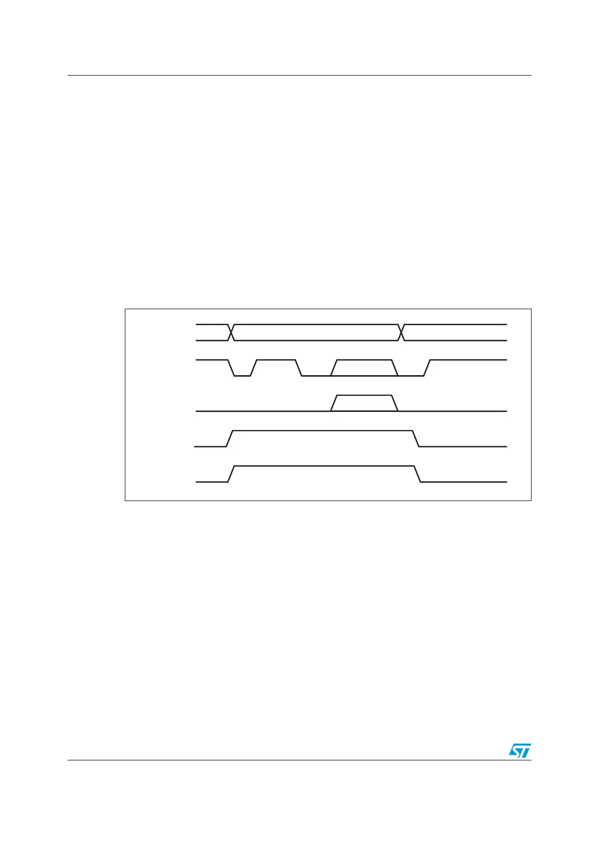
Figure 324. B-device HNP
1. DPPULLDOWN = signal from core to PHY to enable/disable the pull-down on the DP line inside the PHY.
DMPULLDOWN = signal from core to PHY to enable/disable the pull-down on the DM line inside the PHY.
1. The A-device sends the SetFeature b_hnp_enable descriptor to enable HNP support.
The OTG_FS controller’s ACK response indicates that it supports HNP. The application
must set the device HNP enable bit in the OTG Control and status register to indicate
HNP support.
The application sets the HNP request bit in the OTG Control and status register to
indicate to the OTG_FS controller to initiate HNP.
2. When it has finished using the bus, the A-device suspends by writing the Port suspend
bit in the host port control and status register.
The OTG_FS controller sets the Early suspend bit in the Core interrupt register after 3
ms of bus idleness. Following this, the OTG_FS controller sets the USB suspend bit in
the Core interrupt register.
The OTG_FS controller disconnects and the A-device detects SE0 on the bus,
indicating HNP. The OTG_FS controller asserts the DP pull down and DM pull down in
the PHY to indicate its assumption of the host role.
ai15684
OTG core
DP
DM
DPPULLDOWN
DMPULLDOWN
HostDevice Device
1
Suspend 2
3
45
Reset
6
Traffic 7
8
Connect
Traffic
 Loading...


