Inter-integrated circuit (I
2
C) interface RM0008
728/1096 Doc ID 13902 Rev 12
Communication flow
In Master mode, the I
2
C interface initiates a data transfer and generates the clock signal. A
serial data transfer always begins with a start condition and ends with a stop condition. Both
start and stop conditions are generated in master mode by software.
In Slave mode, the interface is capable of recognizing its own addresses (7 or 10-bit), and
the General Call address. The General Call address detection may be enabled or disabled
by software.
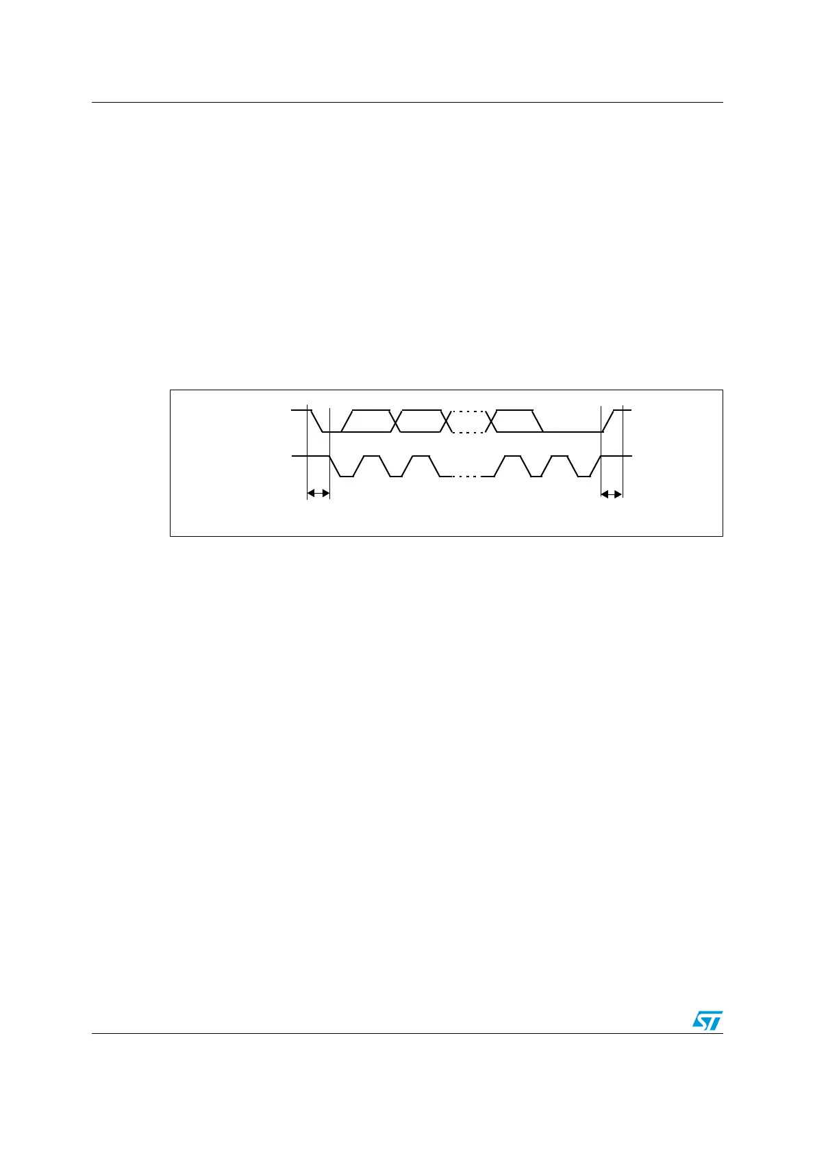
Data and addresses are transferred as 8-bit bytes, MSB first. The first byte(s) following the
start condition contain the address (one in 7-bit mode, two in 10-bit mode). The address is
always transmitted in Master mode.
A 9th clock pulse follows the 8 clock cycles of a byte transfer, during which the receiver must
send an acknowledge bit to the transmitter. Refer to Figure 268.
Figure 268. I
2
C bus protocol
Acknowledge may be enabled or disabled by software. The I
2
C interface addresses (dual
addressing 7-bit/ 10-bit and/or general call address) can be selected by software.
The block diagram of the I
2
C interface is shown in Figure 269.
SCL
SDA
12 8 9
MSB
ACK
Stop
Start
condition
condition
 Loading...


