Low-, medium-, high- and XL-density reset and clock control (RCC) RM0008
88/1096 Doc ID 13902 Rev 12
1. Reset generated when entering Standby mode:
This type of reset is enabled by resetting nRST_STDBY bit in User Option Bytes. In this
case, whenever a Standby mode entry sequence is successfully executed, the device
is reset instead of entering Standby mode.
2. Reset when entering Stop mode:
This type of reset is enabled by resetting nRST_STOP bit in User Option Bytes. In this
case, whenever a Stop mode entry sequence is successfully executed, the device is
reset instead of entering Stop mode.
For further information on the User Option Bytes, refer to the STM32F10xxx Flash
programming manual.
7.1.2 Power reset
A power reset is generated when one of the following events occurs:
1. Power-on/power-down reset (POR/PDR reset)
2. When exiting Standby mode
A power reset sets all registers to their reset values except the Backup domain (see
Figure 4)
These sources act on the NRST pin and it is always kept low during the delay phase. The
RESET service routine vector is fixed at address
0x0000_0004 in the memory map.
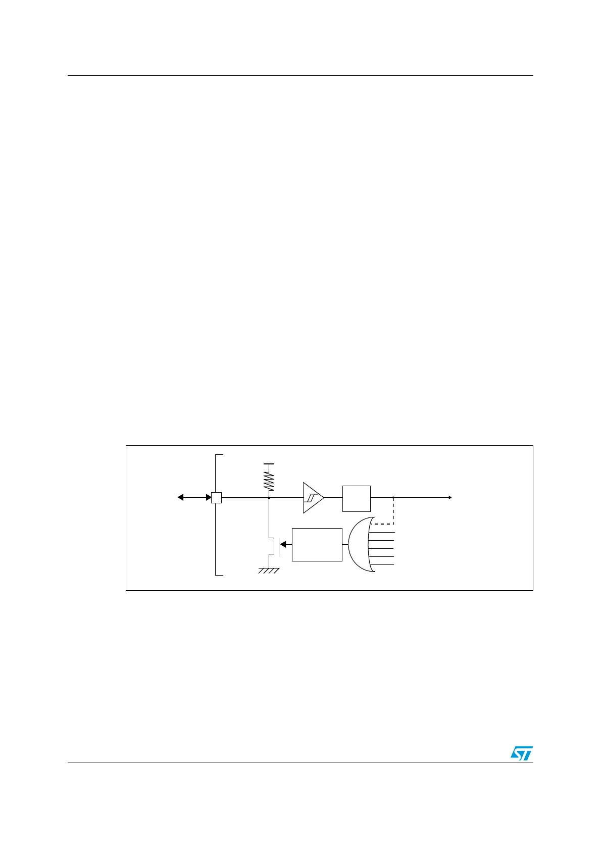
The system reset signal provided to the device is output on the NRST pin. The pulse
generator guarantees a minimum reset pulse duration of 20 µs for each reset source
(external or internal reset). In case of an external reset, the reset pulse is generated while
the NRST pin is asserted low.
Figure 7. Simplified diagram of the reset circuit
7.1.3 Backup domain reset
The backup domain has two specific resets that affect only the backup domain (see
Figure 4).
A backup domain reset is generated when one of the following events occurs:
1. Software reset, triggered by setting the BDRST bit in the Backup domain control
register (RCC_BDCR).
2. V
DD
or V
BAT
power on, if both supplies have previously been powered off.
.234
2
05
6
$$
6
$$!
77$'RESET
)7$'RESET
0ULSE
GENERATOR
0OWERRESET
%XTERNAL
RESET
MINS
3YSTEMRESET
&ILTER
3OFTWARERESET
,OWPOWERMANAGEMENTRESET
AIB
 Loading...


