RM0008 Connectivity line devices: reset and clock control (RCC)
Doc ID 13902 Rev 12 129/1096
8.2.10 Clock-out capability
The microcontroller clock output (MCO) capability allows the clock to be output onto the
external MCO pin. The configuration registers of the corresponding GPIO port must be
programmed in alternate function mode. One of 8 clock signals can be selected as the MCO
clock.
● SYSCLK
● HSI
● HSE
● PLL clock divided by 2 selected
● PLL2 clock selected
● PLL3 clock divided by 2 selected
● XT1 external 3-25 MHz oscillator clock selected (for Ethernet)
● PLL3 clock selected (for Ethernet)
The selected clock to output onto MCO must not exceed 50 MHz (the maximum I/O speed).
The selection is controlled by the MCO[3:0] bits of the Clock configuration register
(RCC_CFGR).
8.3 RCC registers
Refer to Section 2.1 on page 46 for a list of abbreviations used in register descriptions.
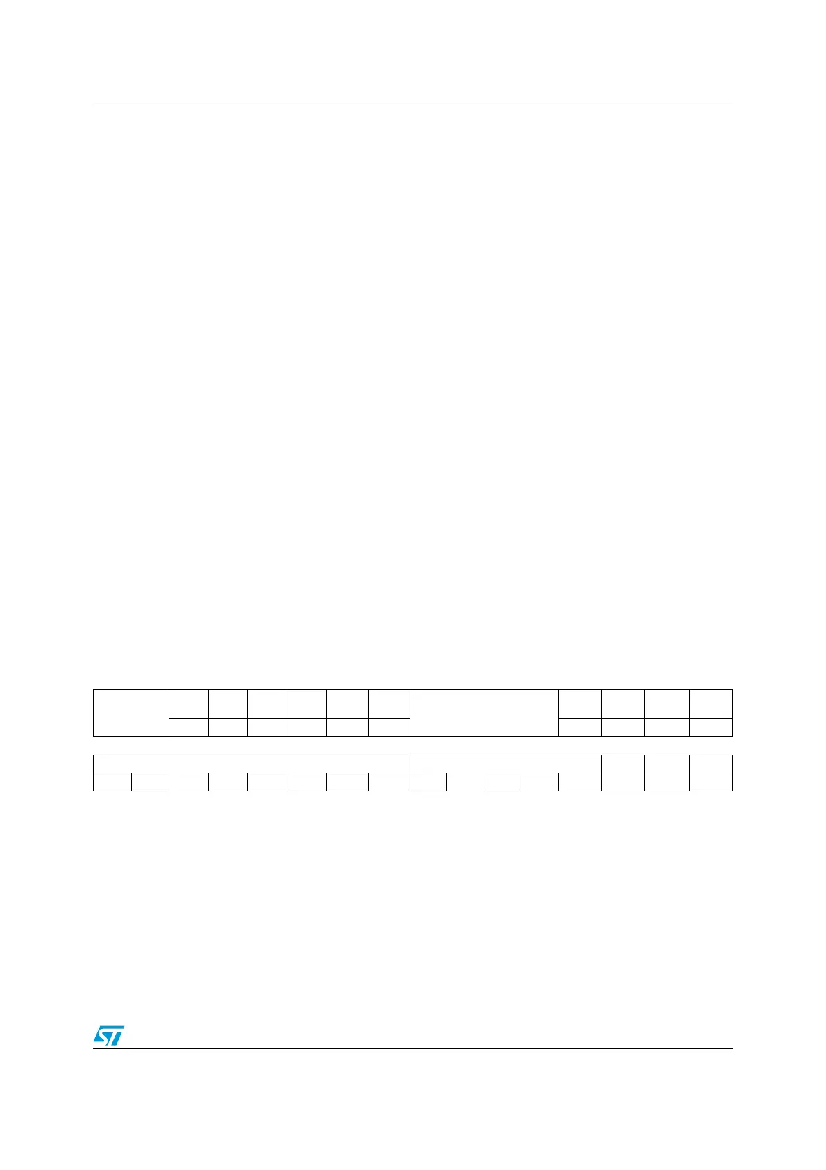
8.3.1 Clock control register (RCC_CR)
Address offset: 0x00
Reset value: 0x0000 XX83 where X is undefined.
Access: no wait state, word, half-word and byte access
31 30 29 28 27 26 25 24 23 22 21 20 19 18 17 16
Reserved
PLL3
RDY
PLL3
ON
PLL2
RDY
PLL2
ON
PLLRDY PLLON
Reserved
CSSON HSEBYP HSERDY HSEON
r rw r rw r rw rw rw r rw
15 14 13 12 11 10 9 8 7 6 5 4 3 2 1 0
HSICAL[7:0] HSITRIM[4:0]
Res.
HSIRDY HSION
r r r r r r r r rwrwrwrw rw r rw
Bits 31:30 Reserved, always read as 0.
Bit 29 PLL3RDY: PLL3 clock ready flag
Set by hardware to indicate that the PLL3 is locked.
0: PLL3 unlocked
1: PLL3 locked
Bit 28 PLL3ON: PLL3 enable
Set and cleared by software to enable PLL3.
Cleared by hardware when entering Stop or Standby mode.
0: PLL3 OFF
1: PLL3 ON
 Loading...


