RM0008 Controller area network (bxCAN)
Doc ID 13902 Rev 12 631/1096
Time-triggered communication option
● Disable automatic retransmission mode
● 16-bit free running timer
● Time Stamp sent in last two data bytes
Management
● Maskable interrupts
● Software-efficient mailbox mapping at a unique address space
Dual CAN (connectivity line only)
● CAN1: Master bxCAN for managing the communication between a Slave bxCAN and
the 512-byte SRAM memory
● CAN2: Slave bxCAN, with no direct access to the SRAM memory.
● The two bxCAN cells share the 512-byte SRAM memory (see Figure 222 on page 633)
Note: In low, medium-, high- and XL-density devices the USB and CAN share a dedicated 512-
byte SRAM memory for data transmission and reception, and so they cannot be used
concurrently (the shared SRAM is accessed through CAN and USB exclusively). The USB
and CAN can be used in the same application but not at the same time.
24.3 bxCAN general description
In today’s CAN applications, the number of nodes in a network is increasing and often
several networks are linked together via gateways. Typically the number of messages in the
system (and thus to be handled by each node) has significantly increased. In addition to the
application messages, Network Management and Diagnostic messages have been
introduced.
● An enhanced filtering mechanism is required to handle each type of message.
Furthermore, application tasks require more CPU time, therefore real-time constraints
caused by message reception have to be reduced.
● A receive FIFO scheme allows the CPU to be dedicated to application tasks for a long
time period without losing messages.
The standard HLP (Higher Layer Protocol) based on standard CAN drivers requires an
efficient interface to the CAN controller.
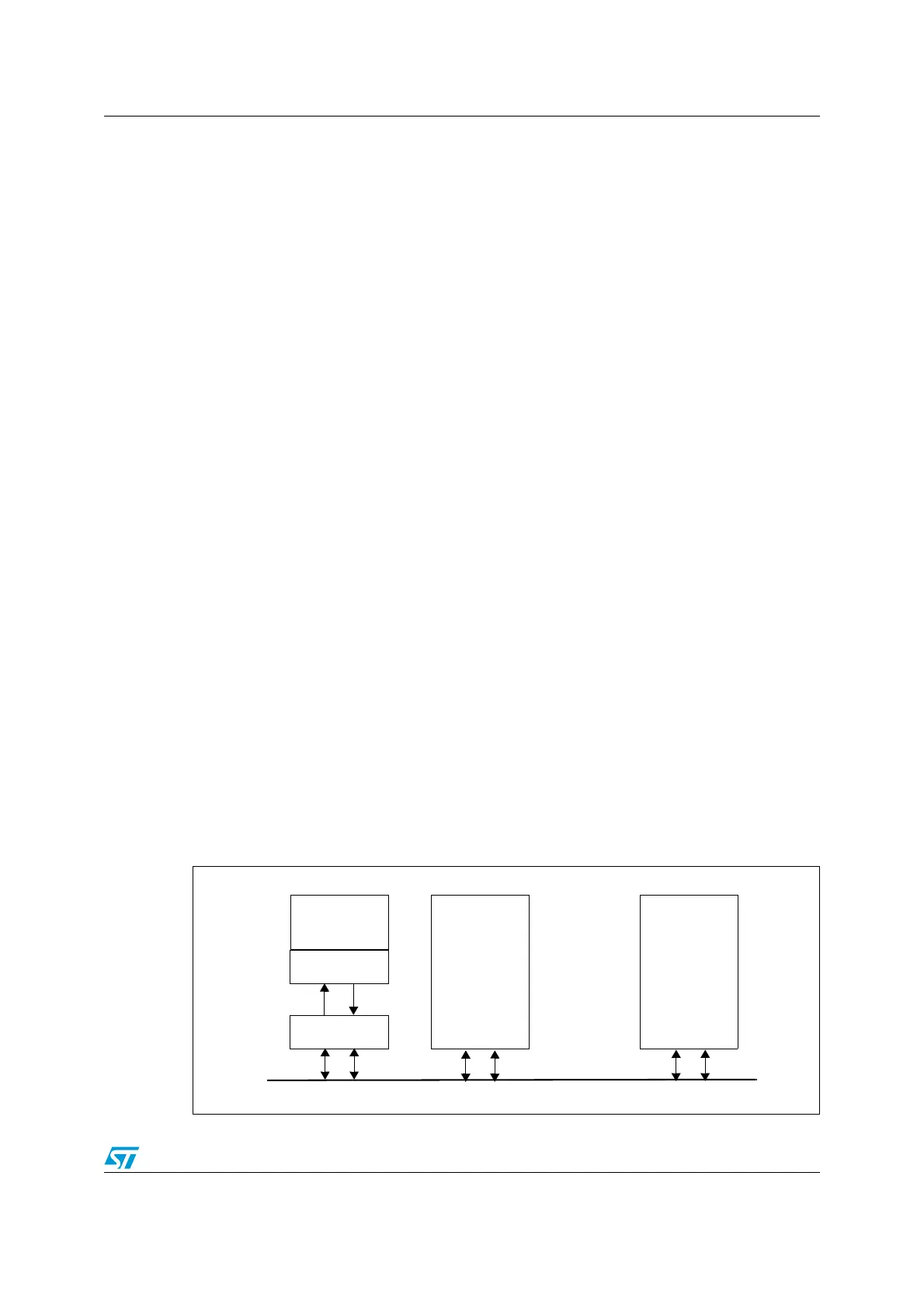
Figure 221. CAN network topology
CAN node 1
CAN node 2
CAN node n
CAN
CAN
High
Low
CANCAN
Rx Tx
CAN
Transceiver
CAN
Controller
MCU
CAN Bus
Application
 Loading...


